Infiniti QX56 (JA60). Manual — part 880

SN
SONAR SYSTEM SYMPTOMS
SN-45
< SYMPTOM DIAGNOSIS >
C
D
E
F
G
H
I
J
K
L
M
B
A
O
P
SYMPTOM DIAGNOSIS
SONAR SYSTEM SYMPTOMS
Symptom Table
INFOID:0000000005146213
Symptom
Repair order
When the sonar system is OFF, the OFF indicator does not light
and the sonar buzzer does not sound.
1.
Check sonar system OFF switch. Refer to
SN-19, "Diagnosis Procedure (With
2.
Check harness and connections for sonar system OFF
switch.
3.
Replace sonar control unit. Refer to
.
When the sonar system is OFF, the OFF indicator lamp does not
light but the sonar buzzer does sound.
1.
Check sonar system OFF switch. Refer to
sis Procedure (With Rear Sonar System)"
or
nosis Procedure (With Front and Rear Sonar System)"
.
2.
Check harness and connections for sonar system OFF indi-
cator lamp.
3.
Replace sonar control unit.
When the sonar system is OFF, the sonar buzzer does not sound
but the OFF indicator lamp lights.
1.
SN-17, "Diagnosis Procedure (With Front and Rear
2.
Check harness and connections between sonar buzzer and
sonar control unit.
3.
Replace sonar control unit.
When sonar system is ON, the sonar system OFF indicator lamp
lights up and the sonar buzzer sounds intermittently (for about 4
seconds). (Rear sonar system only)
1.
Check harnesses between sonar sensors and sonar control
unit for an open condition.
2.
Check sonar sensors. Refer to
3.
Replace sonar control unit.
The sonar system still operates when the sonar system is OFF.
1.
Replace sonar control unit.
When the transmission gear selector lever is in the R position and
the sonar system is ON, the rear sonar system does not operate.
1.
Check transmissin range switch. Refer to
.
2.
Check back-up lamp relay.
3.
Check related harness and connections for back-up lamp re-
lay.
4.
Replace sonar control unit.
When the transmission gear selector lever is in a forward drive
gear and the sonar system is ON, the front sonar system does not
operate. (With front and rear sonar system only)
1.
Check harness and connections between sonar control unit
and combination meter.
2.
Replace sonar control unit.
Sonar system OFF indicator lamp lights up and buzzer sounds al-
though there are no obstacles within the detection range.
1.
Check sonar sensors.
2.
Check harness and connections between sonar sensors
and sonar control unit.
3.
Replace sonar control unit.
The sonar sensors do not detect objects in the detectable range.
1.
Check sonar sensors.
2.
Replace sonar control unit.
SN-46
< PRECAUTION >
PRECAUTION
PRECAUTION
PRECAUTION
Precaution for Supplemental Restraint System (SRS) "AIR BAG" and "SEAT BELT
PRE-TENSIONER"
INFOID:0000000005403331
The Supplemental Restraint System such as “AIR BAG” and “SEAT BELT PRE-TENSIONER”, used along
with a front seat belt, helps to reduce the risk or severity of injury to the driver and front passenger for certain
types of collision. This system includes seat belt switch inputs and dual stage front air bag modules. The SRS
system uses the seat belt switches to determine the front air bag deployment, and may only deploy one front
air bag, depending on the severity of a collision and whether the front occupants are belted or unbelted.
Information necessary to service the system safely is included in the SR and SB section of this Service Man-
ual.
WARNING:
• To avoid rendering the SRS inoperative, which could increase the risk of personal injury or death in
the event of a collision which would result in air bag inflation, all maintenance must be performed by
an authorized NISSAN/INFINITI dealer.
• Improper maintenance, including incorrect removal and installation of the SRS, can lead to personal
injury caused by unintentional activation of the system. For removal of Spiral Cable and Air Bag
Module, see the SR section.
• Do not use electrical test equipment on any circuit related to the SRS unless instructed to in this
Service Manual. SRS wiring harnesses can be identified by yellow and/or orange harnesses or har-
ness connectors.
PRECAUTIONS WHEN USING POWER TOOLS (AIR OR ELECTRIC) AND HAMMERS
WARNING:
• When working near the Airbag Diagnosis Sensor Unit or other Airbag System sensors with the Igni-
tion ON or engine running, DO NOT use air or electric power tools or strike near the sensor(s) with a
hammer. Heavy vibration could activate the sensor(s) and deploy the air bag(s), possibly causing
serious injury.
• When using air or electric power tools or hammers, always switch the Ignition OFF, disconnect the
battery, and wait at least 3 minutes before performing any service.
Precaution Necessary for Steering Wheel Rotation After Battery Disconnect
INFOID:0000000005403332
NOTE:
• This Procedure is applied only to models with Intelligent Key system and NATS (NISSAN ANTI-THEFT SYS-
TEM).
• Remove and install all control units after disconnecting both battery cables with the ignition knob in the
″LOCK″ position.
• Always use CONSULT-III to perform self-diagnosis as a part of each function inspection after finishing work.
If DTC is detected, perform trouble diagnosis according to self-diagnostic results.
For models equipped with the Intelligent Key system and NATS, an electrically controlled steering lock mech-
anism is adopted on the key cylinder.
For this reason, if the battery is disconnected or if the battery is discharged, the steering wheel will lock and
steering wheel rotation will become impossible.
If steering wheel rotation is required when battery power is interrupted, follow the procedure below before
starting the repair operation.
OPERATION PROCEDURE
1. Connect both battery cables.
NOTE:
Supply power using jumper cables if battery is discharged.
2. Use the Intelligent Key or mechanical key to turn the ignition switch to the
″ACC″ position. At this time, the
steering lock will be released.
3. Disconnect both battery cables. The steering lock will remain released and the steering wheel can be
rotated.
4. Perform the necessary repair operation.
SN
PRECAUTION
SN-47
< PRECAUTION >
C
D
E
F
G
H
I
J
K
L
M
B
A
O
P
5. When the repair work is completed, return the ignition switch to the
″LOCK″ position before connecting
the battery cables. (At this time, the steering lock mechanism will engage.)
6. Perform a self-diagnosis check of all control units using CONSULT-III.
SN-48
< PREPARATION >
PREPARATION
PREPARATION
PREPARATION
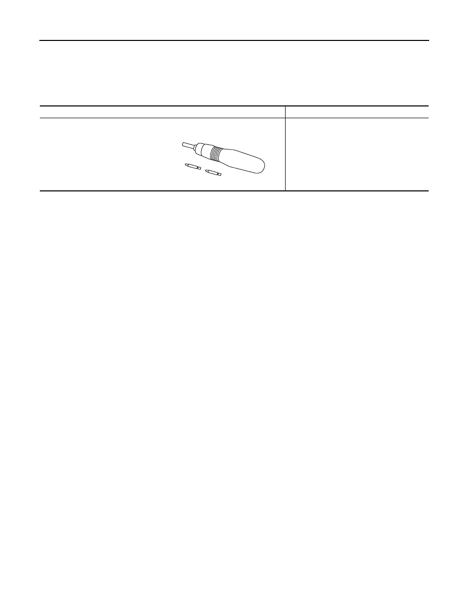
Commercial Service Tool
INFOID:0000000005146215
Tool name
Description
Power tool
Loosening bolts and nuts.
PBIC0191E
Нет комментариевНе стесняйтесь поделиться с нами вашим ценным мнением.
Текст