Infiniti QX56 (JA60). Manual — part 410

EC-292
< COMPONENT DIAGNOSIS >
[VK56DE]
P0850 PNP SWITCH
P0850 PNP SWITCH
Component Description
INFOID:0000000005149331
When the selector lever position is P or N, park/neutral position (PNP) signal from the TCM is sent to ECM.
When the gear position is P or N, transmission range switch is ON.
On Board Diagnosis Logic
INFOID:0000000005149332
DTC Confirmation Procedure
INFOID:0000000005149333
CAUTION:
Always drive vehicle at a safe speed.
NOTE:
If DTC Confirmation Procedure has been previously conducted, always perform the following procedure
before conducting the next step.
1. Turn ignition switch OFF and wait at least 10 seconds.
2. Turn ignition switch ON.
3. Turn ignition switch OFF and wait at least 10 seconds.
WITH CONSULT-III
1. Turn ignition switch ON.
2. Select “P/N POSI SW” in “DATA MONITOR” mode with CONSULT-III. Then check the “P/N POSI SW” sig-
nal under the following conditions.
If NG, go to
If OK, go to following step.
3. Select “DATA MONITOR” mode with CONSULT-III.
4. Start engine and warm it up to normal operating temperature.
5. Maintain the following conditions for at least 60 consecutive seconds.
6. Check 1st trip DTC.
7. If 1st trip DTC is detected, go to
Overall Function Check
INFOID:0000000005149334
Use this procedure to check the overall function of the park/neutral position (PNP) signal circuit. During this
check, a 1st trip DTC might not be confirmed.
WITH GST
DTC No.
Trouble diagnosis name
DTC detecting condition
Possible cause
P0850
0850
Park/neutral position
switch
The signal of the park/neutral position (PNP)
signal is not changed in the process of engine
starting and driving.
• Harness or connectors
[The park/neutral position (PNP) signal
circuit is open or shorted.]
• Combination meter
• TCM
Position (Selector lever)
Known-good signal
N or P position
ON
Except the above position
OFF
ENG SPEED
1,000 - 6,375 rpm
COOLAN TEMP/S
More than 70
°C (158°F)
B/FUEL SCHDL
2.0 - 31.8 msec
VHCL SPEED SE
More than 64 km/h (40 MPH)
Selector lever
Suitable position
P0850 PNP SWITCH
EC-293
< COMPONENT DIAGNOSIS >
[VK56DE]
C
D
E
F
G
H
I
J
K
L
M
A
EC
N
P
O
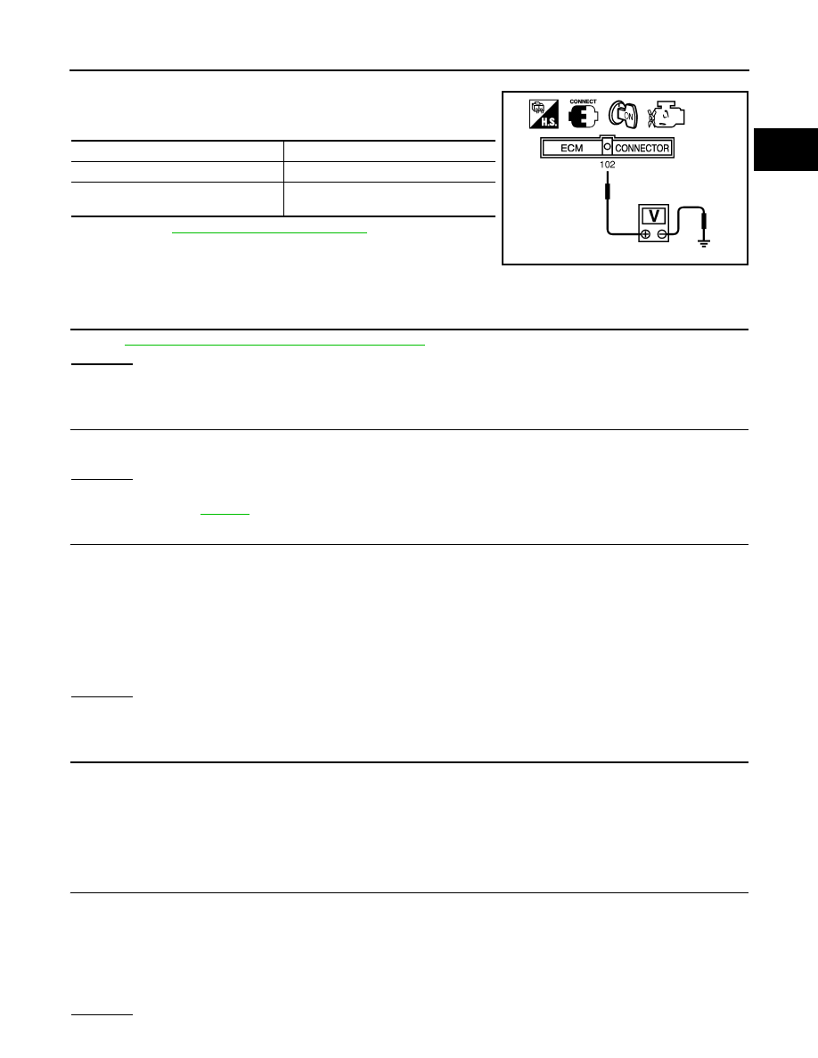
1. Turn ignition switch ON.
2. Check voltage between ECM terminal 102 (PNP signal) and
ground under the following conditions.
3. If NG, go to
Diagnosis Procedure
INFOID:0000000005149335
1.
CHECK DTC WITH TCM
TM-30, "OBD-II Diagnostic Trouble Code (DTC)"
.
OK or NG
OK
>> GO TO 2.
NG
>> Repair or replace.
2.
CHECK STARTING SYSTEM
Turn ignition switch OFF, then turn it to START.
Does starter motor operate?
Yes or No
Yes
>> GO TO 3.
No
>> Refer to
3.
CHECK PNP INPUT SIGNAL CIRCUIT FOR OPEN AND SHORT-I
1. Turn ignition switch OFF.
2. Disconnect A/T assembly harness connector.
3. Disconnect combination meter harness connector.
4. Check harness continuity between A/T assembly terminal 9 and combination meter terminal 8.
Refer to Wiring Diagram.
5. Also check harness for short to ground and short to power.
OK or NG
OK
>> GO TO 5.
NG
>> GO TO 4.
4.
DETECT MALFUNCTIONING PART
Check the following.
• Harness connectors F14, E5
• Harness connectors E152, M31
• Harness for open or short between A/T assembly and combination meter
>> Repair open circuit or short to ground or short to power in harness or connectors.
5.
CHECK PNP INPUT SIGNAL CIRCUIT FOR OPEN AND SHORT-II
1. Disconnect ECM harness connector.
2. Check harness continuity between ECM terminal 102 and combination meter terminal 7.
Refer to Wiring Diagram.
3. Also check harness for short to ground and short to power.
OK or NG
Condition (Gear position)
Voltage (Known-good data)
P or N position
Approx. 0
Except the above position
BATTERY VOLTAGE
(11 - 14 V)
MBIB0043E
Continuity should exist.
Continuity should exist.

EC-294
< COMPONENT DIAGNOSIS >
[VK56DE]
P0850 PNP SWITCH
OK
>> GO TO 7.
NG
>> GO TO 6.
6.
DETECT MALFUNCTIONING PART
Check the following.
• Harness connectors M31, E152
• Harness for open or short between ECM and combination meter
>> Repair open circuit or short to ground or short to power in harness or connectors.
7.
CHECK PNP INPUT SIGNAL CIRCUIT FOR OPEN AND SHORT-III
1. Disconnect TCM harness connector.
2. Check harness continuity between TCM terminal 8 and A/T assembly terminal 9.
Refer to Wiring Diagram.
3. Also check harness for short to ground and short to power.
OK or NG
OK
>> GO TO 8.
NG
>> Repair open circuit or short to ground or short to power in harness or connectors.
8.
CHECK INTERMITTENT INCIDENT
GI-35, "How to Check Terminal"
and
GI-38, "Intermittent Incident"
OK or NG
OK
>> GO TO 9.
NG
>> Repair or replace.
9.
REPLACE COMBINATION METER
MWI-100, "Removal and Installation"
>> INSPECTION END
Continuity should exist.
P1140, P1145 IVT CONTROL POSITION SENSOR
EC-295
< COMPONENT DIAGNOSIS >
[VK56DE]
C
D
E
F
G
H
I
J
K
L
M
A
EC
N
P
O
P1140, P1145 IVT CONTROL POSITION SENSOR
Component Description
INFOID:0000000005149336
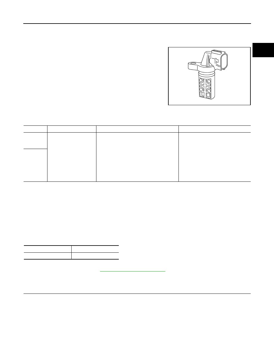
Intake valve timing control position sensors are located in the front of
cylinder heads in both bank 1 and bank 2.
This sensor uses a Hall IC.
The cam position is determined by the intake camshaft sprocket con-
cave (in four places). The ECM provides feedback to the intake valve
timing control for appropriate target valve open-close timing accord-
ing to drive conditions based on detected cam position.
On Board Diagnosis Logic
INFOID:0000000005149337
DTC Confirmation Procedure
INFOID:0000000005149338
1. If DTC Confirmation Procedure has been previously conducted, always perform the following procedure
before conducting the next step.
a. Turn ignition switch OFF and wait at least 10 seconds.
b. Turn ignition switch ON.
c. Turn ignition switch OFF and wait at least 10 seconds.
2. Turn ignition switch ON.
3. Maintain the following conditions for at least 10 seconds.
4. Check 1st trip DTC.
5. If 1st trip DTC is detected, go to
Diagnosis Procedure
INFOID:0000000005149339
1.
CHECK GROUND CONNECTIONS
1. Turn ignition switch OFF.
2. Loosen and retighten three ground screws on the body.
SEF359Z
DTC No.
Trouble diagnosis name
DTC detecting condition
Possible cause
P1140
1140
(Bank 1)
Intake valve timing control
position sensor circuit
An excessively high or low voltage from the
sensor is sent to ECM.
• Harness or connectors
(Intake valve timing control position
sensor circuit is open or shorted)
• Intake valve timing control position
sensor
• Crankshaft position sensor (POS)
• Camshaft position sensor (PHASE)
• Accumulation of debris to the signal
pick-up portion of the camshaft sprock-
et
P1145
1145
(Bank 2)
ENG SPEED
More than idle speed
Selector lever
P or N position
Нет комментариевНе стесняйтесь поделиться с нами вашим ценным мнением.
Текст