Infiniti QX56 (JA60). Manual — part 66
AV-72
< COMPONENT DIAGNOSIS >
[AUDIO SYSTEM]
POWER SUPPLY AND GROUND CIRCUIT
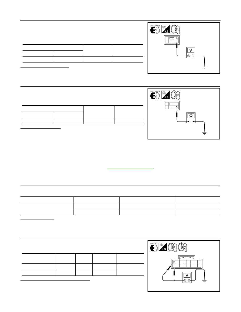
1. Turn ignition switch OFF.
2. Disconnect subwoofer connector.
3. Check voltage between subwoofer harness connector B72 ter-
minal 6 and ground.
Is battery voltage present?
YES
>> GO TO 3.
NO
>> Check harness between subwoofer and fuse.
3.
CHECK GROUND CIRCUIT
1. Turn ignition switch OFF.
2. Check continuity between subwoofer harness connector B72
terminal 5 and ground.
Does continuity exist?
YES
>> Inspection End.
NO
>> Repair harness or connector.
REAR VIEW CAMERA CONTROL UNIT
REAR VIEW CAMERA CONTROL UNIT : Diagnosis Procedure
INFOID:0000000005146306
Regarding Wiring Diagram information, refer to
.
1.
CHECK FUSE
Check that the following fuses of the rear view camera control unit are not blown.
Are the fuses OK?
YES
>> GO TO 2.
NO
>> Be sure to eliminate cause of malfunction before installing new fuse.
2.
CHECK POWER SUPPLY CIRCUIT
Check voltage between rear view camera control unit harness con-
nector B73 and ground.
Are the voltage readings as specified?
YES
>> GO TO 3.
NO
>> Check harness between rear view camera control unit
and fuse.
(+)
(-)
Voltage (approx.)
Connector
Terminal
B72
6
Ground
Battery voltage
ALNIA0367GB
(+)
(-)
Continuity
Connector
Terminal
B72
5
Ground
Yes
ALNIA0368GB
Unit
Terminals
Signal name
Fuse No.
Rear view camera control unit
1
Battery power
31
2
Ignition switch ACC or ON
4
Signal name
Connector
Terminal
Ignition switch
position
Value (Approx.)
Battery power supply
B73
1
OFF
Battery voltage
ACC power supply
2
ACC
ALLIA0244ZZ
AV
POWER SUPPLY AND GROUND CIRCUIT
AV-73
< COMPONENT DIAGNOSIS >
[AUDIO SYSTEM]
C
D
E
F
G
H
I
J
K
L
M
B
A
O
P
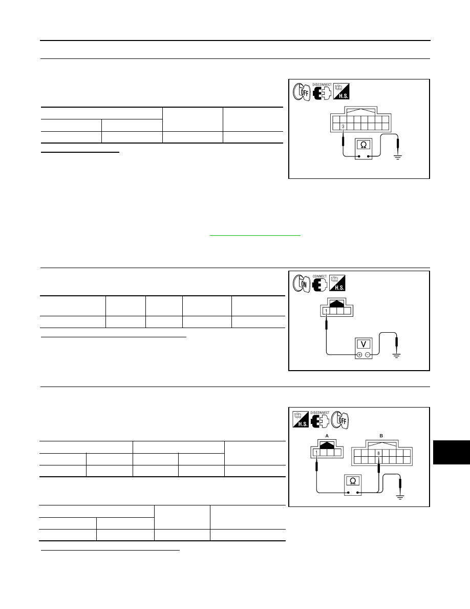
3.
CHECK GROUND CIRCUIT
1. Turn ignition switch OFF.
2. Disconnect rear view camera control unit connector.
3. Check continuity between rear view camera control unit harness
connector B31 terminal 3 and ground.
Does continuity exist?
YES
>> Inspection End.
NO
>> Repair harness or connector.
REAR VIEW CAMERA
REAR VIEW CAMERA : Diagnosis Procedure
INFOID:0000000005146307
Regarding Wiring Diagram information, refer to
.
1.
CHECK POWER SUPPLY CIRCUIT (REAR VIEW CAMERA SIDE)
Check voltage between rear view camera harness connector D504
and ground.
Is voltage reading approximately 6 volts?
YES
>> GO TO 4.
NO
>> GO TO 2.
2.
CHECK POWER SUPPLY CIRCUIT (CONTINUITY)
1. Turn ignition switch OFF.
2. Disconnect rear view camera and rear view camera control unit connectors.
3. Check continuity between rear view camera harness connector
D504 (A) terminal 1 and rear view camera control unit harness
connector B73 (B) terminal 8.
4. Check continuity between rear view camera harness connector
D504 (A) terminal 1 and ground.
Are continuity test results as specified?
YES
>> GO TO 3.
NO
>> Repair harness or connector.
(+)
(-)
Continuity
Connector
Terminal
B31
3
Ground
Yes
ALLIA0245ZZ
Signal name
Connector
Terminal
Transmission
position
Value (Approx.)
Camera ON signal
D504
1
Reverse
6V
ALLIA0243ZZ
A
B
Continuity
Connector
Terminal
Connector
Terminal
D504
1
B73
8
Yes
A
—
Continuity
Connector
Terminal
D504
1
Ground
No
ALLIA0246ZZ
AV-74
< COMPONENT DIAGNOSIS >
[AUDIO SYSTEM]
POWER SUPPLY AND GROUND CIRCUIT
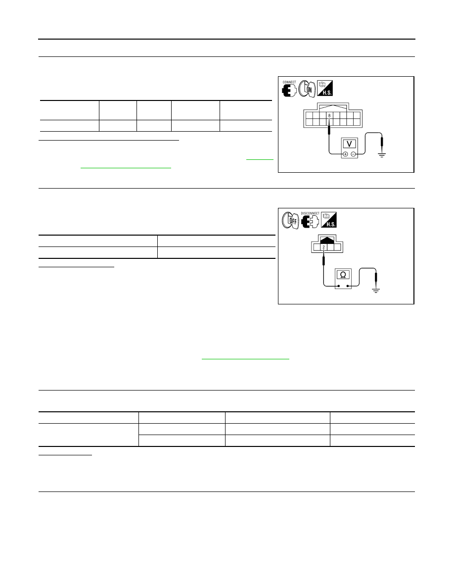
3.
CHECK POWER SUPPLY CIRCUIT (REAR VIEW CAMERA CONTROL UNIT SIDE)
1. Connect rear view camera control unit harness connector.
2. Turn ignition switch ON.
3. Check voltage between rear view camera control unit harness
connector B73 and ground.
Is voltage reading approximately 6 volts?
YES
>> Inspection End.
NO
>> Replace rear view camera control unit. Refer to
.
4.
CHECK GROUND CIRCUIT
1. Turn ignition switch OFF.
2. Disconnect rear view camera harness connector.
3. Check continuity between rear view camera harness connector
D504 terminal 2 and ground.
Does continuity exist?
YES
>> Inspection End.
NO
>> Repair harness or connector.
DVD PLAYER
DVD PLAYER : Diagnosis Procedure
INFOID:0000000005146308
Regarding Wiring Diagram information, refer to
.
1.
CHECK FUSE
Check that the DVD player fuse is not blown.
Is the fuse OK?
YES
>> GO TO 2.
NO
>> If fuse is blown, be sure to eliminate cause of malfunction before installing new fuse.
2.
POWER SUPPLY CIRCUIT CHECK
Signal name
Connector
Terminal
Transmission
position
Value (Approx.)
Camera ON signal
B73
8
Reverse
6V
ALLIA0247ZZ
Signal name
Continuity
Ground
Yes
ALLIA0248ZZ
Unit
Terminal
Signal name
Fuse No.
DVD player
21
Battery power
31
24
Ignition switch ACC or ON
4
AV
POWER SUPPLY AND GROUND CIRCUIT
AV-75
< COMPONENT DIAGNOSIS >
[AUDIO SYSTEM]
C
D
E
F
G
H
I
J
K
L
M
B
A
O
P
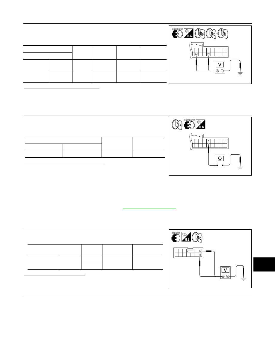
1. Disconnect DVD player connector M205.
2. Check voltage between the DVD player connector M205 and
ground.
Are the voltage results as specified?
YES
>> GO TO 3.
NO
>> • Check connector housings for disconnected or loose terminals.
• Repair harness or connector.
3.
GROUND CIRCUIT CHECK
1. Ignition OFF.
2. Check continuity between DVD player harness connector M205
terminal 5 and ground.
Are the continuity results as specified?
YES
>> Inspection End.
NO
>> Repair DVD player ground.
VIDEO MONITOR
VIDEO MONITOR : Diagnosis Procedure
INFOID:0000000005146309
Regarding Wiring Diagram information, refer to
.
1.
CHECK POWER SUPPLY CIRCUIT
Check voltage between video monitor harness connector R202 and
ground.
Does specified voltage exist?
YES
>> GO TO 3.
NO
>> GO TO 2.
2.
CHECK POWER SUPPLY CIRCUIT
(+)
(-)
OFF
ACC
ON
Connector
Terminal
M205
21
Ground
Batter volt-
age
Battery
voltage
Battery volt-
age
24
0V
Battery
voltage
Battery volt-
age
ALNIA0325GB
(+)
(-)
Continuity
Connector
Terminal
M205
5
Ground
Yes
ALNIA0326GB
Signal name
Connector
Terminal
Ignition switch
position
Value (Approx.)
Display B+
R202
11
ACC
12V
12
ALNIA0328GB
Нет комментариевНе стесняйтесь поделиться с нами вашим ценным мнением.
Текст