Infiniti QX56 (JA60). Manual — part 949
TM-98
< COMPONENT DIAGNOSIS >
TOW MODE SWITCH
TOW MODE SWITCH
Description
INFOID:0000000005148683
When tow mode switch is “ON”, tow mode switch signals are sent to TCM from combination meter by CAN
communication line.Then it`s a tow mode condition.
Diagnosis Procedure
INFOID:0000000005148684
1.
CHECK CAN COMMUNICATION LINE
Perform the self-diagnosis. Refer to
TM-32, "CONSULT-III Function (TRANSMISSION)"
.
Is any malfunction in the CAN communication indicated in the results?
YES
>> Check CAN communication line. Refer to
.
NO
>> GO TO 2.
2.
CHECK POWER SOURCE
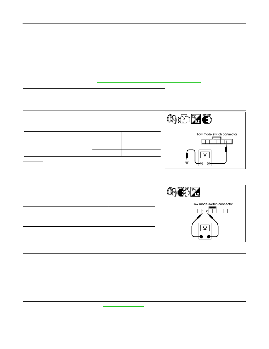
1. Turn ignition switch “ON”. (Do not start engine.)
2. Check the voltage between tow mode switch connector M258
terminal 1 and ground.
OK or NG
OK
>> INSPECTION END
NG
>> GO TO 3.
3.
CHECK TOW MODE SWITCH
1. Turn ignition switch “OFF”.
2. Disconnect tow mode switch connector.
3. Check continuity between tow mode switch terminals 1 and 2.
OK or NG
OK
>> GO TO 4.
NG
>> Repair or replace tow mode switch.
4.
DETECT MALFUNCTIONING ITEM
Check the following items. If any items are damaged, repair or replace damaged parts.
• Harness for short or open between combination meter connector terminal 35 and tow mode switch connec-
tor terminal 1.
• Harness for short or open between tow mode switch connector terminal 2 and ground.
OK or NG
OK
>> GO TO 5.
NG
>> Repair or replace damaged parts.
5.
CHECK COMBINATION METER
Check the combination meter. Refer to
OK or NG
OK
>> INSPECTION END
NO
>> Repair or replace damaged parts.
Condition
Tow mode
switch
Data (Approx.)
When ignition switch is turned to “ON”
ON
0V
OFF
Battery voltage
SCIA5156E
Condition
Continuity
Tow mode switch “ON”
Yes
Tow mode switch “OFF”
No
SCIA5584E
A/T SHIFT LOCK SYSTEM
TM-99
< COMPONENT DIAGNOSIS >
C
E
F
G
H
I
J
K
L
M
A
B
TM
N
O
P
A/T SHIFT LOCK SYSTEM
Description
INFOID:0000000005203382
Terminals And Reference Values
INFOID:0000000005148686
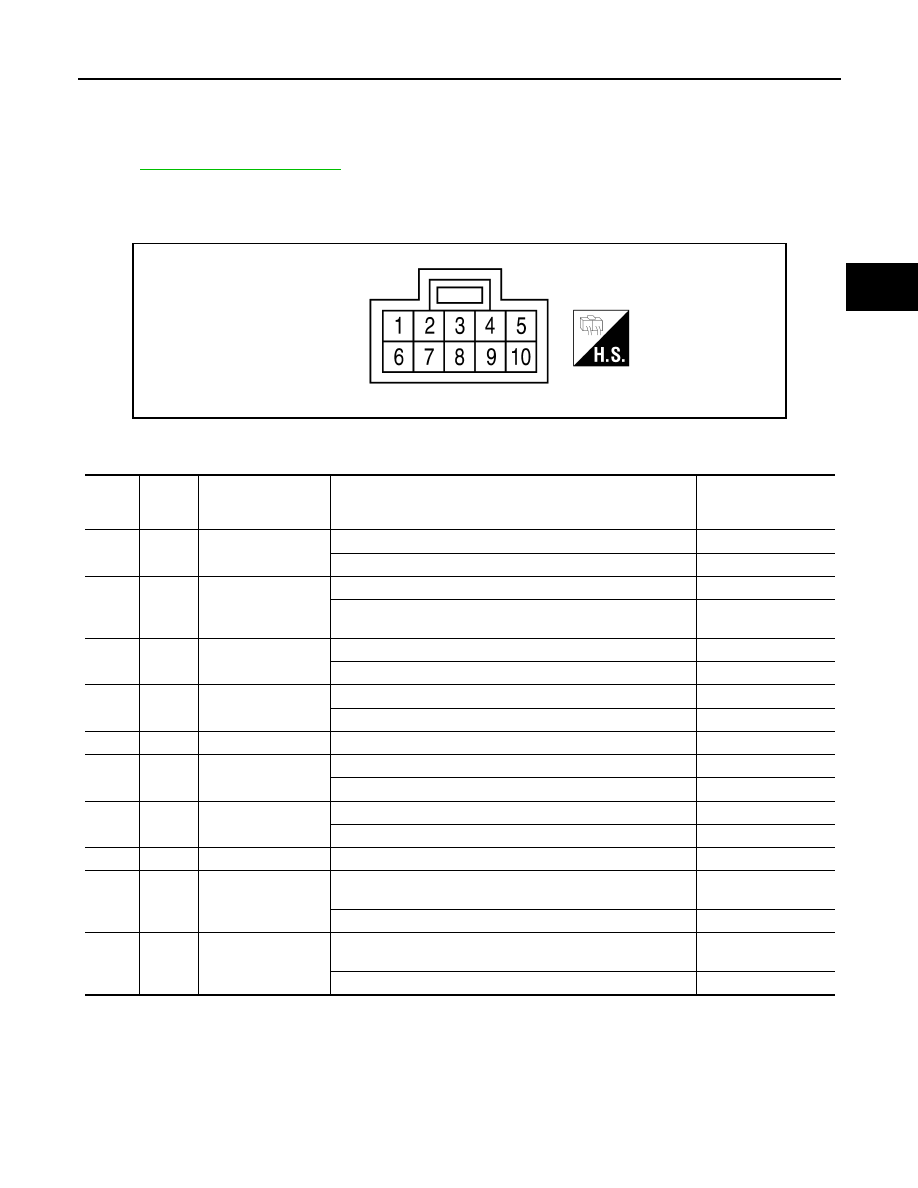
SHIFT LOCK HARNESS CONNECTOR TERMINALS LAYOUT
SHIFT LOCK CONTROL UNIT INSPECTION TABLE
Data are reference values.
NOTE:
Confirm that the pointer swings only momentarily because the output time is so short. If the inspection is done with an oscilloscope, it
should be observed that the power source voltage lasts for 3.5 to 10 ms.
AWDIA0043ZZ
TER-
MINAL
NO.
WIRE
COLOR
ITEM
CONDITION
VOLTAGE
(Approx.)
1
P
Power source
Ignition switch: “ON”
Battery voltage
Ignition switch: “OFF”
Battery voltage
2
L/R
Park position switch
(Intelligent Key sys-
tem)
Selector lever in “P” position
0V
Except above with ignition knob switch in “PUSHED” or “ON”
position
Battery voltage
3
GR
Park position switch
(shift selector)
Selector lever in “P” position
0V
Except above
Battery voltage
4
R/G
Stop lamp switch
Brake pedal applied
Battery voltage
Brake pedal released
0V
5
W/R
Vehicle speed signal
—
—
6
G/R
Ignition signal
Ignition switch: “ON”
Battery voltage
Ignition switch: “OFF”
0V
7
R/W
Shift lock solenoid
Brake pedal applied with ignition knob switch in “ON” position
0V
Except above
Battery voltage
8
B
Ground
—
—
9
R
Key lock solenoid
Selector lever in any position except “P”, and ignition knob
switch turned from “ON” to “OFF”
Battery voltage for ap-
prox. 0.1 sec. (Note)
Except above
0V
10
W/G
Key unlock solenoid
Ignition knob switch in “PUSHED” position.
Battery voltage for ap-
prox. 0.1 sec. (Note)
Except above
0V
TM-100
< COMPONENT DIAGNOSIS >
A/T SHIFT LOCK SYSTEM
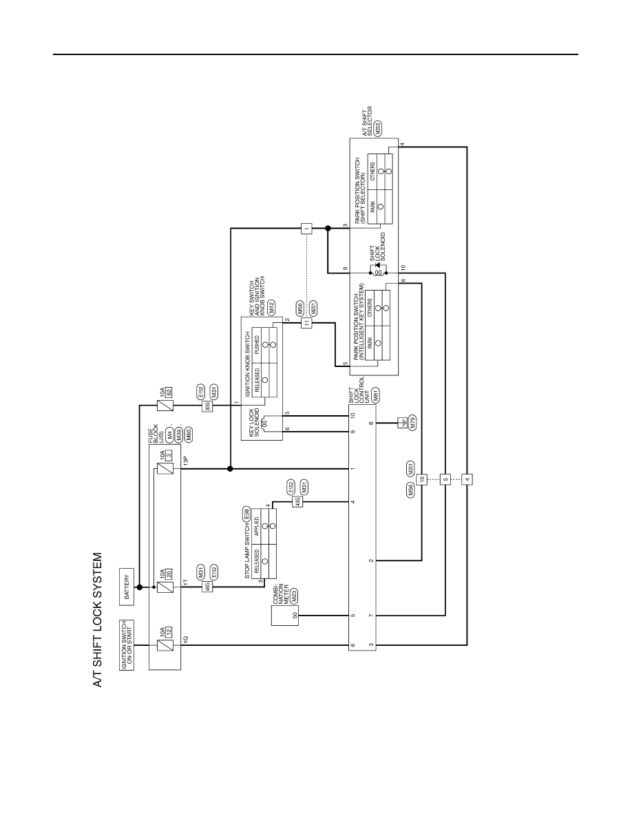
Wiring Diagram - A/T SHIFT LOCK SYSTEM -
INFOID:0000000005148685
ABDWA0116GB
A/T SHIFT LOCK SYSTEM
TM-101
< COMPONENT DIAGNOSIS >
C
E
F
G
H
I
J
K
L
M
A
B
TM
N
O
P
AADIA0120GB
Нет комментариевНе стесняйтесь поделиться с нами вашим ценным мнением.
Текст