Infiniti QX56 (JA60). Manual — part 387
EC-200
< COMPONENT DIAGNOSIS >
[VK56DE]
P0327, P0328, P0332, P0333 KS
7.
DETECT MALFUNCTIONING PART
Check the following.
• Harness connectors F26, F101
• Harness connectors F14, E5
• Harness for open or short between knock sensor terminal 2 and ground
>> Repair open circuit or short power in harness or connectors.
8.
CHECK INTERMITTENT INCIDENT
GI-35, "How to Check Terminal"
and
GI-38, "Intermittent Incident"
>> INSPECTION END
Component Inspection
INFOID:0000000005149218
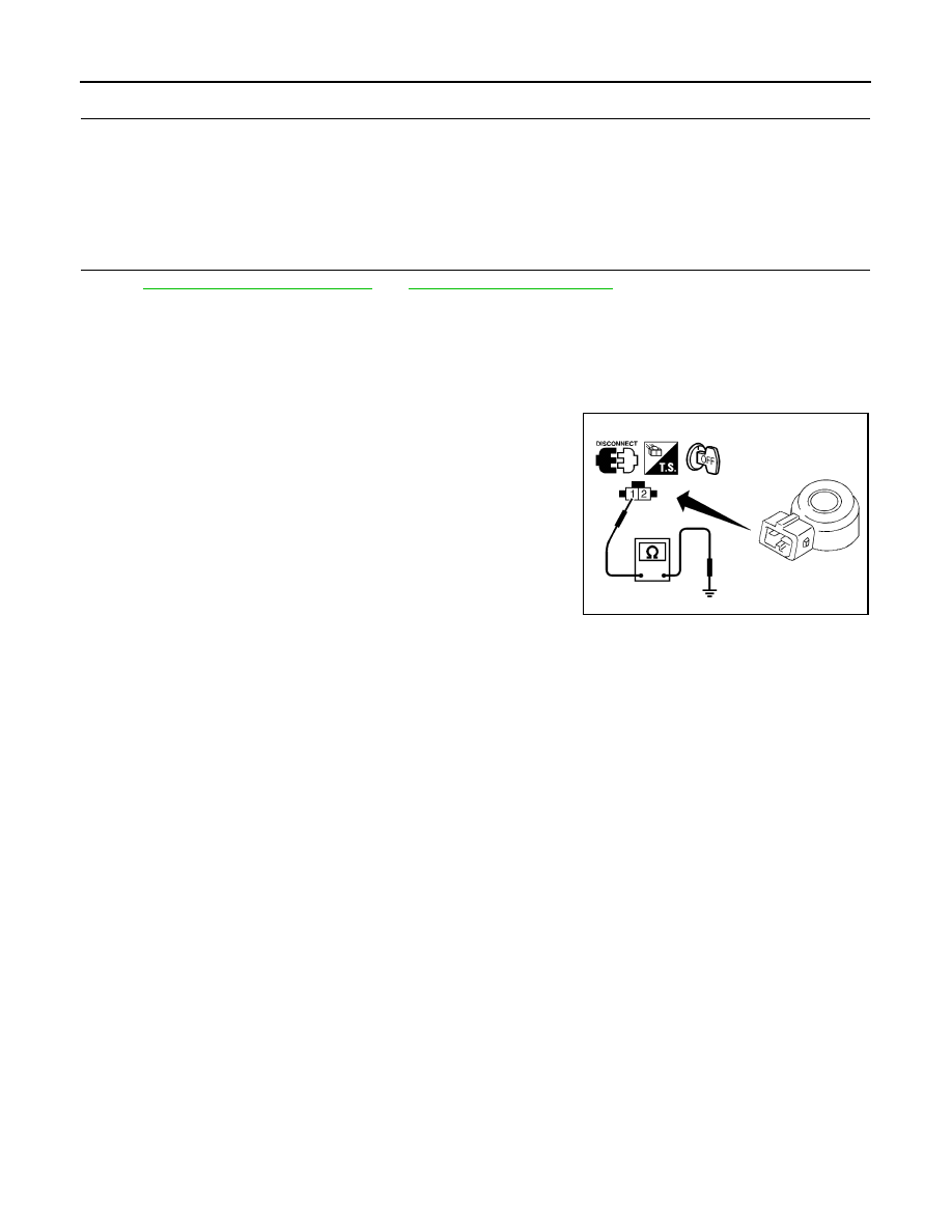
KNOCK SENSOR
Check resistance between knock sensor terminal 1 and ground.
NOTE:
It is necessary to use an ohmmeter which can measure more
than 10 M
Ω.
CAUTION:
Do not use any knock sensors that have been dropped or phys-
ically damaged. Use only new ones.
Resistance: Approximately 532 - 588 k
Ω [at 20°C (68°F)]
SEF227W
P0335 CKP SENSOR (POS)
EC-201
< COMPONENT DIAGNOSIS >
[VK56DE]
C
D
E
F
G
H
I
J
K
L
M
A
EC
N
P
O
P0335 CKP SENSOR (POS)
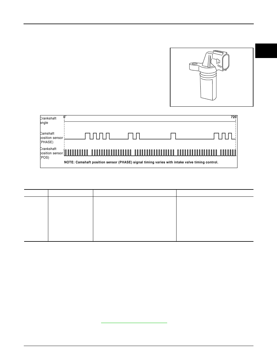
Component Description
INFOID:0000000005149219
The crankshaft position sensor (POS) is located on the A/T assem-
bly facing the gear teeth (cogs) of the signal plate. It detects the fluc-
tuation of the engine revolution.
The sensor consists of a permanent magnet and Hall IC.
When the engine is running, the high and low parts of the teeth
cause the gap with the sensor to change.
The changing gap causes the magnetic field near the sensor to
change.
Due to the changing magnetic field, the voltage from the sensor
changes.
The ECM receives the voltage signal and detects the fluctuation of
the engine revolution.
ECM receives the signals as shown in the figure.
On Board Diagnosis Logic
INFOID:0000000005149220
DTC Confirmation Procedure
INFOID:0000000005149221
NOTE:
If DTC Confirmation Procedure has been previously conducted, always perform the following procedure
before conducting the next step.
1. Turn ignition switch OFF and wait at least 10 seconds.
2. Turn ignition switch ON.
3. Turn ignition switch OFF and wait at least 10 seconds.
TESTING CONDITION:
Before performing the following procedure, confirm that battery voltage is more than 10.5 V with igni-
tion switch ON.
1. Crank engine for at least 2 seconds and run it for at least 5 seconds at idle speed.
2. Check 1st trip DTC.
3. If 1st trip DTC is detected, go to
Diagnosis Procedure
INFOID:0000000005149222
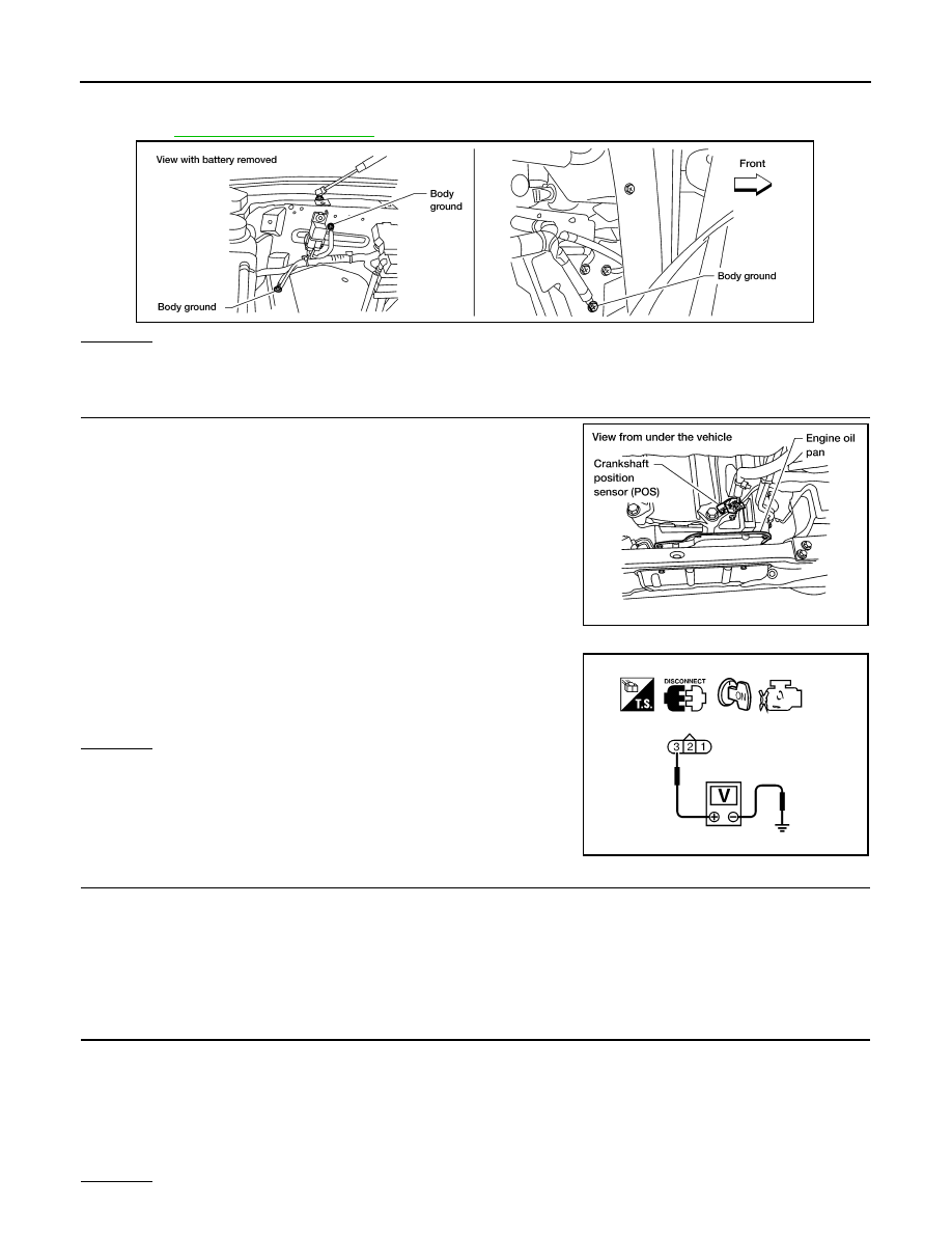
1.
CHECK GROUND CONNECTIONS
PBIB0562E
PBIB3459E
DTC No.
Trouble diagnosis name
DTC detecting condition
Possible cause
P0335
0335
Crankshaft position sen-
sor (POS) circuit
• The crankshaft position sensor (POS) signal
is not detected by the ECM during the first
few seconds of engine cranking.
• The proper pulse signal from the crankshaft
position sensor (POS) is not sent to ECM
while the engine is running.
• The crankshaft position sensor (POS) signal
is not in the normal pattern during engine run-
ning.
• Harness or connectors
(The sensor circuit is open or shorted)
• Crankshaft position sensor (POS)
• Signal plate
EC-202
< COMPONENT DIAGNOSIS >
[VK56DE]
P0335 CKP SENSOR (POS)
1. Turn ignition switch OFF.
2. Loosen and retighten three ground screws on the body.
OK or NG
OK
>> GO TO 2.
NG
>> Repair or replace ground connections.
2.
CHECK CRANKSHAFT POSITION (CKP) SENSOR (POS) POWER SUPPLY CIRCUIT
1. Disconnect crankshaft position (CKP) sensor (POS) harness
connector.
2. Turn ignition switch ON.
3. Check voltage between CKP sensor (POS) terminal 3 and
ground with CONSULT-III or tester.
OK or NG
OK
>> GO TO 4.
NG
>> GO TO 3.
3.
DETECT MALFUNCTIONING PART
Check the following.
• Harness connectors F32, E2
• Harness for open or short between crankshaft position sensor (POS) and ECM
• Harness for open or short between crankshaft position sensor (POS) and IPDM E/R
>> Repair open circuit or short to ground or short to power in harness or connectors.
4.
CHECK CKP SENSOR (POS) GROUND CIRCUIT FOR OPEN AND SHORT
1. Turn ignition switch OFF.
2. Check harness continuity between CKP sensor (POS) terminal 1 and ground.
Refer to Wiring Diagram.
3. Also check harness for short to power.
OK or NG
BBIA0354E
BBIA0367E
Voltage: Battery voltage
SEF481Y
Continuity should exist.
P0335 CKP SENSOR (POS)
EC-203
< COMPONENT DIAGNOSIS >
[VK56DE]
C
D
E
F
G
H
I
J
K
L
M
A
EC
N
P
O
OK
>> GO TO 6.
NG
>> GO TO 5.
5.
DETECT MALFUNCTIONING PART
Check the following.
• Harness connectors F32, E2
• Harness for open or short between crankshaft position sensor (POS) and ground
>> Repair open circuit or short to power in harness or connectors.
6.
CHECK CKP SENSOR (POS) INPUT SIGNAL CIRCUIT FOR OPEN AND SHORT
1. Disconnect ECM harness connector.
2. Check harness continuity between ECM terminal 13 and CKP sensor (POS) terminal 2.
Refer to Wiring Diagram.
3. Also check harness for short to ground and short to power.
OK or NG
OK
>> GO TO 7.
NG
>> Repair open circuit or short to ground or short to power in harness or connectors.
7.
CHECK CRANKSHAFT POSITION SENSOR (POS)
EC-203, "Component Inspection"
OK or NG
OK
>> GO TO 8.
NG
>> Replace crankshaft position sensor (POS).
8.
CHECK GEAR TOOTH
Visually check for chipping signal plate gear tooth.
OK or NG
OK
>> GO TO 9.
NG
>> Replace the signal plate.
9.
CHECK INTERMITTENT INCIDENT
GI-35, "How to Check Terminal"
GI-38, "Intermittent Incident"
>> INSPECTION END
Component Inspection
INFOID:0000000005149223
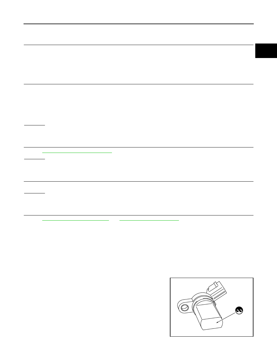
CRANKSHAFT POSITION SENSOR (POS)
1. Loosen the fixing bolt of the sensor.
2. Disconnect crankshaft position sensor (POS) harness connector.
3. Remove the sensor.
4. Visually check the sensor for chipping.
Continuity should exist.
PBIB0563E
Нет комментариевНе стесняйтесь поделиться с нами вашим ценным мнением.
Текст