Infiniti QX56 (JA60). Manual — part 815
EXHAUST VALVE SOLENOID CIRCUIT
SCS-25
< COMPONENT DIAGNOSIS >
C
D
F
G
H
I
J
K
L
M
A
B
SCS
N
O
P
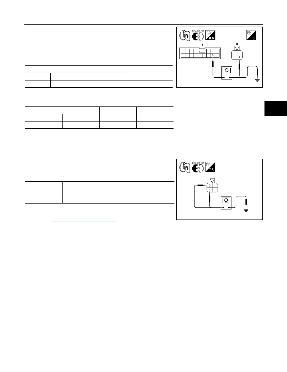
1. Turn ignition switch OFF.
2. Disconnect suspension control unit connector B3 and suspen-
sion air compressor connector C9.
3. Check continuity between suspension control unit connector B3
(A) terminal 9 and suspension air compressor connector C9 (B)
terminal 2.
4. Check continuity between suspension control unit connector B3
(A) terminal 9 and ground.
Are the continuity test results as specified?
YES
>> Replace the suspension control unit. Refer to
RSU-26, "Removal and Installation"
.
NO
>> Repair harness or connector.
3.
CHECK SUSPENSION AIR COMPRESSOR GROUND
1. Turn ignition switch OFF.
2. Check continuity between suspension air compressor connector
C9 terminals 1 and 3 and ground.
Is continuity present?
YES
>> Replace the suspension air compressor. Refer to
24, "Removal and Installation"
.
NO
>> Repair harness or connector.
A
B
Continuity
Connector
Terminal
Connector
Terminal
B3
9
C9
2
Yes
A
—
Continuity
Connector
Terminal
B3
9
Ground
No
ALEIA0037GB
Connector
Terminal
—
Continuity
C9
1
Ground
Yes
3
ALEIA0038GB
SCS-26
< COMPONENT DIAGNOSIS >
CK SUSP WARNING INDICATOR CONTROL CIRCUIT
CK SUSP WARNING INDICATOR CONTROL CIRCUIT
Description
INFOID:0000000005148187
The CK SUSP warning lamp is controlled by a ground signal provided to the combination meter by the sus-
pension control unit.
Component Function Check
INFOID:0000000005148188
1.
CHECK WARNING LAMP OPERATION
CONSULT-III
1. Turn ignition ON.
2. Select "WARNING LAMP" of AIR LEVELIZER active test items.
3. While operating test item, check that the warning lamp activates.
Does the warning lamp operate properly?
YES
>> Warning lamp is operating normally.
NO
>> Refer to
.
Diagnosis Procedure
INFOID:0000000005148189
Regarding Wiring Diagram information, refer to
.
1.
PERFORM SUSPENSION CONTROL SYSTEM SELF-DIAGNOSIS
CONSULT-III
1. Turn ignition ON.
2. Perform SELF DIAGNOSIS function of AIR LEVELIZER system.
Are any DTC's present?
YES
>> Refer to
.
NO
>> • If warning lamp is always ON, GO TO 2.
• If warning lamp is always OFF, GO TO 3
2.
CHECK SUSPENSION CONTROL UNIT WARNING LAMP CONTROL
1. Turn ignition OFF.
2. Disconnect the suspension control unit connector B3.
3. Turn ignition ON.
Does the CK SUSP warning lamp turn ON?
YES
>> GO TO 3.
NO
>> Replace the suspension control unit. Refer to
RSU-26, "Removal and Installation"
.
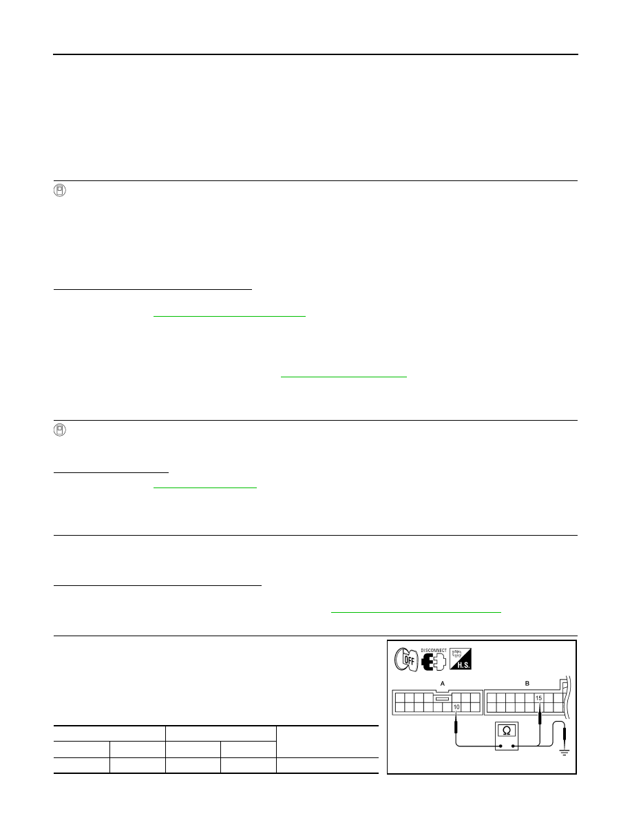
3.
CHECK CONTINUITY OF WARNING LAMP CONTROL CIRCUIT
1. Turn ignition switch OFF.
2. Disconnect suspension control unit connector B3 and combina-
tion meter connector M24.
3. Check continuity between suspension control unit connector B3
(A) terminal 10 and combination meter connector M24 (B) termi-
nal 15.
ON
: Warning lamp turns ON
OFF
: Warning lamp turns OFF
A
B
Continuity
Connector
Terminal
Connector
Terminal
B3
10
M24
15
Yes
ALLIA0693GB

CK SUSP WARNING INDICATOR CONTROL CIRCUIT
SCS-27
< COMPONENT DIAGNOSIS >
C
D
F
G
H
I
J
K
L
M
A
B
SCS
N
O
P
4. Check continuity between suspension control unit connector B3 (A) terminal 10 and ground.
Are the continuity test results as specified?
YES
>> Replace the combination meter. Refer to
MWI-100, "Removal and Installation"
NO
>> Repair harness or connector.
A
—
Continuity
Connector
Terminal
B3
10
Ground
No
SCS-28
< ECU DIAGNOSIS >
SUSPENSION CONTROL UNIT
ECU DIAGNOSIS
SUSPENSION CONTROL UNIT
Reference Value
INFOID:0000000005148190
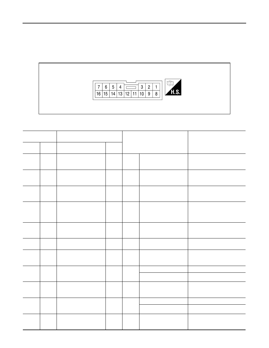
TERMINAL LAYOUT
PHYSICAL VALUES
AWLIA1640ZZ
Terminal
(Wire color)
Description
Condition
Reference value
(Approx.)
+
–
Signal name
Input/
Output
1
(V)
Ground Compressor relay output
Output
Ignition
switch
ON
Air levelizer raising vehicle
ride height
Battery voltage
3
(W)
Ground Height sensor input
Input
Ignition
switch
ON
—
0.2V - 4.8V
5
(R)
Ground
VREF output (height sen-
sor)
Output
Ignition
switch
ON
—
5V
6
(G/R)
Ground IGN power supply
Input
Ignition
switch
ON or
START
—
Battery voltage
7
(W/L)
Ground BAT power supply
Input
Ignition
switch
OFF
—
Battery voltage
8
(G/W)
Ground
Diagnostic K-line
Input/
Output
—
—
—
9
(SB)
Ground Exhaust valve output
Output
Ignition
switch
ON
Air levelizer lowering vehi-
cle ride height (venting)
Battery voltage
10
(BR)
Ground Warning lamp output
Output
Ignition
switch
ON
Warning lamp ON
0V
Warning lamp OFF
Battery voltage
14
(L)
Ground
Height sensor ground
Output
Ignition
switch
ON
—
Less than 0.2V
15
(BR/W)
Ground Generator input
Input
Ignition
switch
ON
Charge light ON
0V
Charge light OFF
Battery voltage
16
(B)
Ground
Suspension control unit
ground
Input
Ignition
switch
ON
—
Less than 0.2V
Нет комментариевНе стесняйтесь поделиться с нами вашим ценным мнением.
Текст