Infiniti QX56 (JA60). Manual — part 529
ADJUSTMENT AND INSPECTION
EXL-145
< ON-VEHICLE REPAIR >
C
D
E
F
G
H
I
J
K
M
A
B
EXL
N
O
P
ON-VEHICLE REPAIR
ADJUSTMENT AND INSPECTION
HEADLAMP
HEADLAMP : Aiming Adjustment
INFOID:0000000005146696
NOTE:
• For details, refer to the regulations in your area.
• If vehicle front body has been repaired and /or the headlamp assembly has been replaced, check headlamp
aiming.
HEADLAMP AIMING
NOTE:
• Before performing aiming adjustment, check the following:
- Ensure all tires are inflated to correct pressure.
- Place vehicle and screen on level surface.
- Ensure there is no load in vehicle other than the driver (or equivalent weight placed in driver's position).
Coolant and engine oil filled to correct level, and fuel tank full.
- Confirm spare tire, jack and tools are properly stowed.
- Aim each headlamp individually and ensure other headlamp beam pattern is blocked from screen.
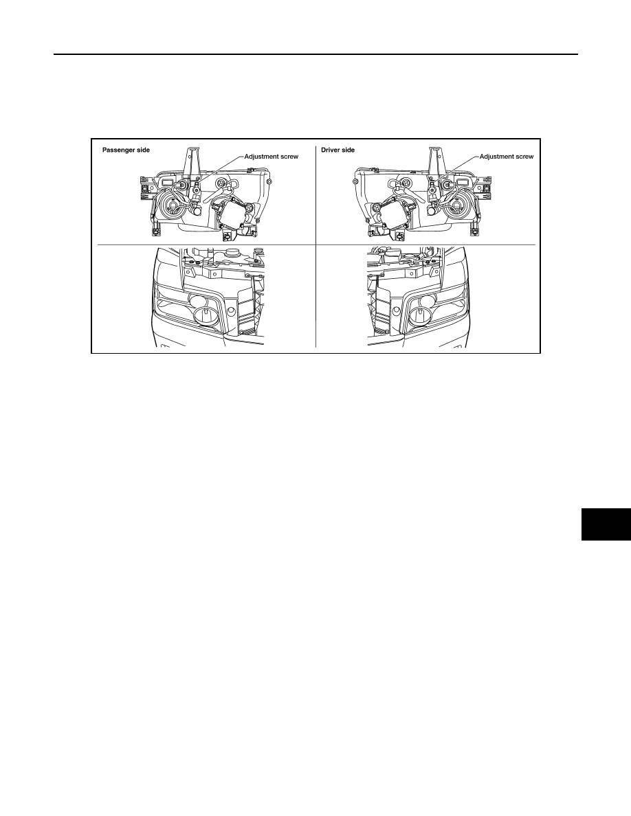
- Use adjusting screw to perform aiming adjustment
WKIA1859E
EXL-146
< ON-VEHICLE REPAIR >
ADJUSTMENT AND INSPECTION
NOTE:
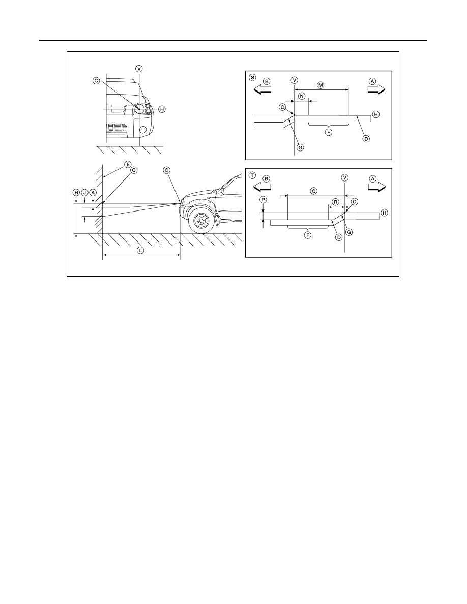
Basic illuminating area for adjustment should be within the range shown on the aiming chart. Adjust head-
lamps accordingly.
LOW BEAM AND HIGH BEAM
1. Turn headlamp low beam on.
2. Use adjusting screw to perform aiming adjustment.
FRONT FOG LAMP
FRONT FOG LAMP : Aiming Adjustment
INFOID:0000000005146697
The fog lamp is a semi-sealed beam type which uses a replaceable halogen bulb. Before performing aiming
adjustment, make sure of the following.
• Keep all tires inflated to correct pressure.
• Place vehicle on level ground.
A.
Right
B.
Left
C.
Center of headlamp bulb (H-V point)
D.
Cutoff line
E.
Screen
F.
Aim evaluation segment
G.
Step
H.
Horizontal center line of headlamp
J.
103 mm (4.06 in.)
K.
37 mm (1.46 in.)
L.
7.62 m (25 ft.)
M.
399 mm (15.71 in.)
N.
133 mm (5.24 in.)
P.
53.2 mm (2.09 in.)
Q.
466 mm (18.35 in.)
R.
200 mm (7.87 in.)
S.
RH headlamp aiming screen
T.
LH headlamp aiming screen
V.
Vertical center line
LKIA0809E
ADJUSTMENT AND INSPECTION
EXL-147
< ON-VEHICLE REPAIR >
C
D
E
F
G
H
I
J
K
M
A
B
EXL
N
O
P
• See that vehicle is unloaded (except for full levels of coolant,
engine oil and fuel, and spare tire, jack, and tools). Have the driver
or equivalent weight placed in driver seat.
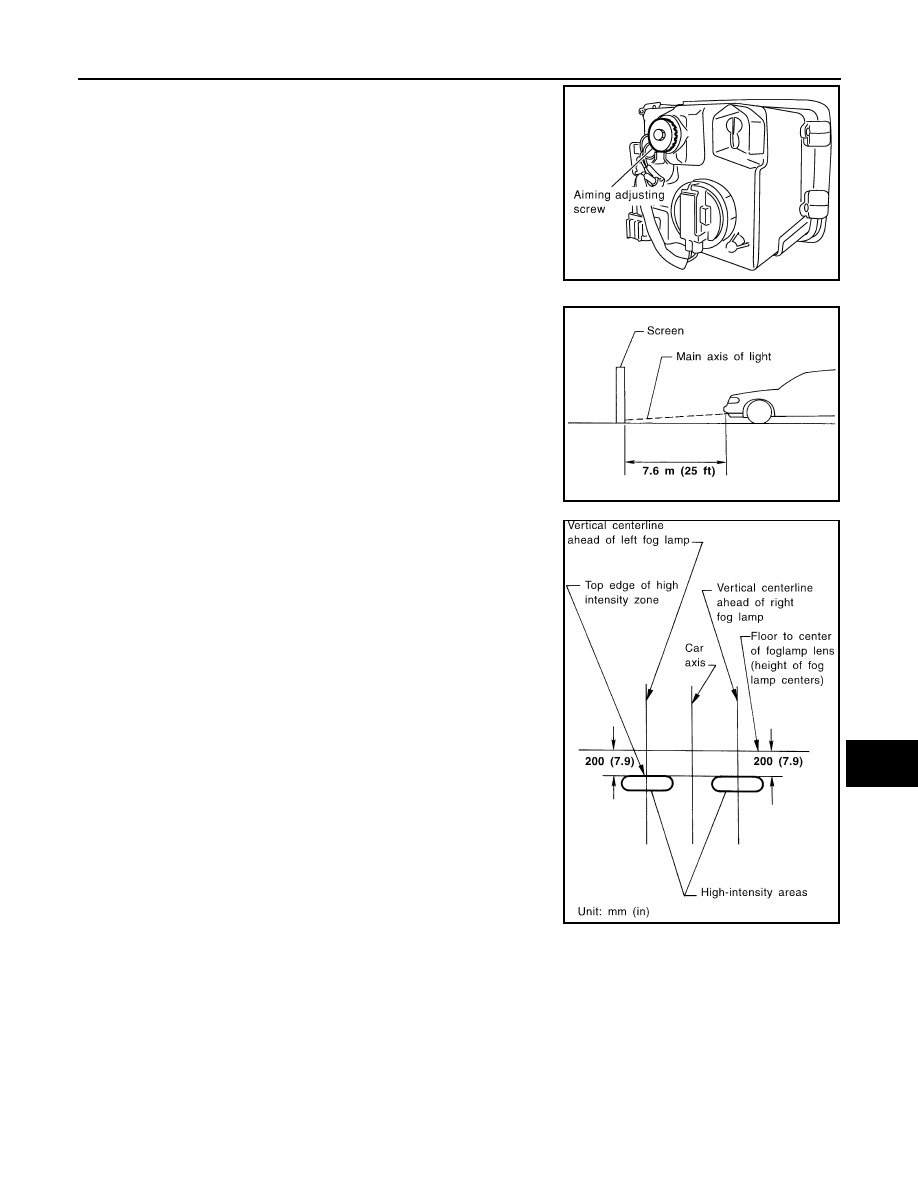
Adjust aiming in the vertical direction by turning the adjustment
screw.
NOTE:
Access adjustment screw from underneath front bumper. Turn screw
clockwise to raise pattern and counterclockwise to lower pattern.
1. Set the distance between the screen and the center of the fog
lamp lens as shown.
2. Turn front fog lamps ON.
3. Adjust front fog lamps using adjusting screw so that the top edge
of the high intensity zone is 200 mm (7.9 in) below the height of
the fog lamp centers as shown.
• When performing adjustment, if necessary, cover the head-
lamps and opposite fog lamp.
SEL350X
MEL327G
MEL328GA
EXL-148
< REMOVAL AND INSTALLATION >
HEADLAMP
REMOVAL AND INSTALLATION
HEADLAMP
Bulb Replacement
INFOID:0000000005146698
CAUTION:
• Disconnect battery negative terminal before touching xenon bulb or headlamp wiring harness
assembly.
• Turn headlamp switch OFF before disconnecting headlamp harness connector.
• Do not touch bulb by hand right after being turned off. Burning may result.
• Do not touch the glass of bulb directly by hand. Keep grease and other oily substances away from it.
• Do not turn xenon bulb ON when xenon bulb is removed from front combination lamp assembly.
• After installing the bulb, be sure to install the bulb socket securely to ensure watertightness.
• Do not leave bulb out of front combination lamp assembly for a long time because dust, moisture,
smoke, etc. may affect the performance of the lamp. When replacing bulb, be sure to replace it with a
new one.
HEADLAMP (OUTER SIDE), FOR LOW BEAM
Removal
1. Position fender protector aside.
2. Turn headlamp switch OFF.
3. Disconnect battery negative terminal.
4. Remove ballast.
5. Disconnect headlamp electrical connector.
6. Release bulb retaining spring and pull bulb straight out.
Installation
Installation is in the reverse order of removal.
HEADLAMP (INNER SIDE), FOR HIGH BEAM
Removal
1. Turn headlamp switch OFF.
2. Disconnect headlamp electrical connector.
3. Turn the bulb counterclockwise to remove it.
Installation
Installation is in the reverse order of removal.
FRONT PARKING LAMP (INNER OR OUTER)
Removal
1. Turn the bulb socket counterclockwise to unlock it.
2. Pull the bulb to remove it from the socket.
Installation
Installation is in the reverse order of removal.
SIDE MARKER LAMP (FRONT)
Removal
1. Position fender protector aside.
2. Turn the side marker lamp (front) bulb socket counterclockwise and remove side marker lamp (front) bulb
socket.
3. Pull to remove side marker lamp (front) from the side marker lamp (front) bulb socket.
Installation
Installation is in the reverse order of removal.
Нет комментариевНе стесняйтесь поделиться с нами вашим ценным мнением.
Текст