Infiniti QX56 (JA60). Manual — part 137
C1143, C1144 STEERING ANGLE SENSOR
BRC-61
< COMPONENT DIAGNOSIS >
[VDC/TCS/ABS]
C
D
E
G
H
I
J
K
L
M
A
B
BRC
N
O
P
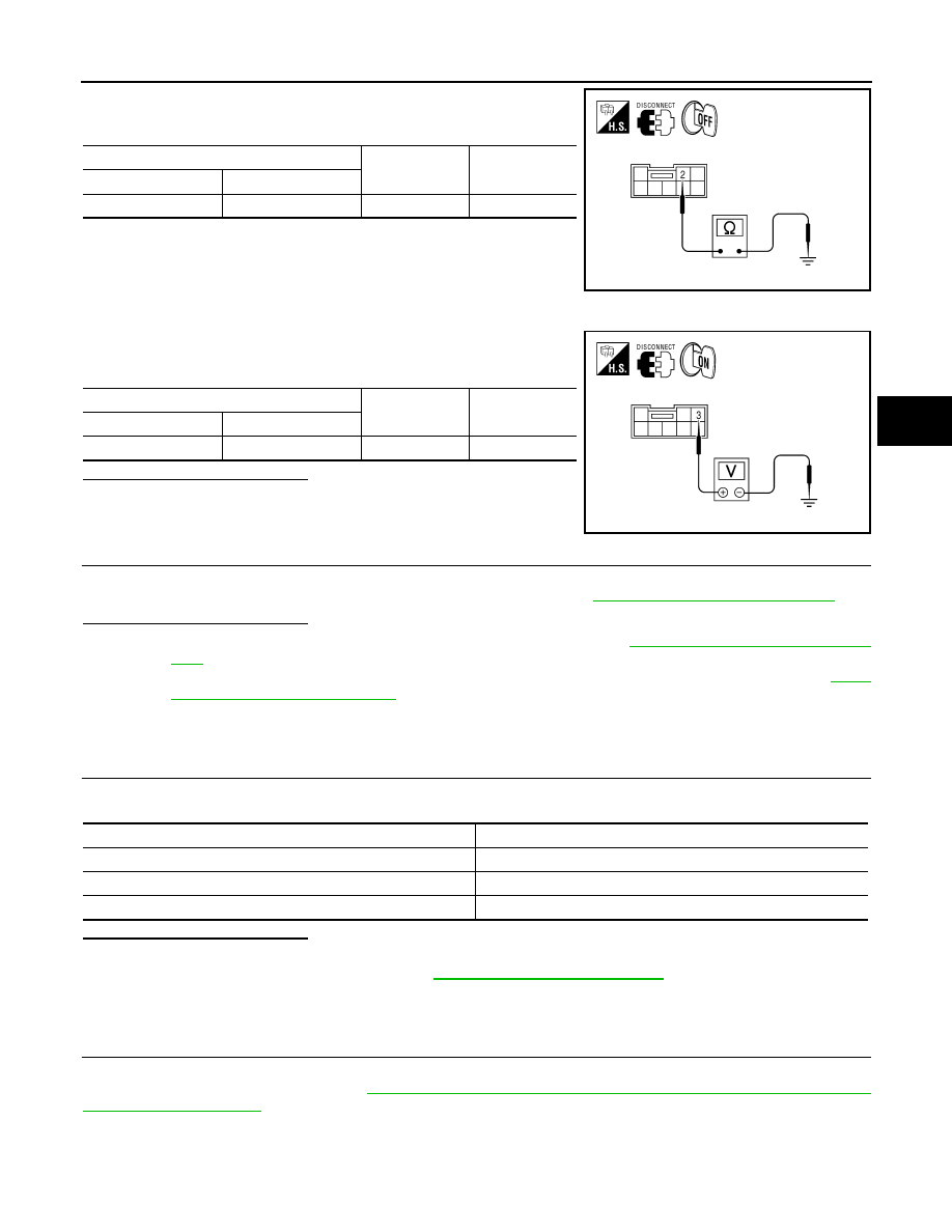
3. Check continuity between steering angle sensor connector M17
terminal 2 and ground.
4. Turn ignition switch ON.
5. Check voltage between steering angle sensor connector M17
terminal 3 and ground.
Is the inspection result normal?
YES
>> GO TO 3
NO
>> Repair or replace malfunctioning components.
3.
CHECK DATA MONITOR
1. Connect the steering angle sensor connector and ABS actuator and electric unit (control unit) connector.
2. Perform the steering angle sensor component inspection. Refer to
BRC-61, "Component Inspection"
.
Is the inspection result normal?
YES
>> Replace ABS actuator and electric unit (control unit). Refer to
BRC-116, "Removal and Installa-
.
NO
>> Replace steering angle sensor and adjust neutral position of steering angle sensor. Refer to
118, "Removal and Installation"
Component Inspection
INFOID:0000000005148026
1.
CHECK DATA MONITOR
Select “STR ANGLE SIG” in “DATA MONITOR” and check steering angle sensor signal.
Is the inspection result normal?
YES
>> Inspection End
NO
>> Go to diagnosis procedure. Refer to
Special Repair Requirement
INFOID:0000000005194918
1.
ADJUSTMENT OF STEERING ANGLE SENSOR NEUTRAL POSITION
Always perform neutral position adjustment for the steering angle sensor when replacing the ABS actuator
and electric unit (control unit). Refer to
BRC-8, "ADJUSTMENT OF STEERING ANGLE SENSOR NEUTRAL
.
>> GO TO 2
Steering angle sensor
—
Continuity
Connector
Terminal
M17
2
Ground
Yes
WFIA0399E
Steering angle sensor
—
Voltage
Connector
Terminal
M17
3
Ground
Battery voltage
AWFIA0023ZZ
Steering condition
STR ANGLE SIG (DATA MONITOR)
Driving straight
±2.5 °
Turn 90
° to right
Approx. +90
°
Turn 90
° to left
Approx.
−90 °
BRC-62
< COMPONENT DIAGNOSIS >
[VDC/TCS/ABS]
C1143, C1144 STEERING ANGLE SENSOR
2.
CALIBRATION OF DECEL G SENSOR
Always perform calibration of decel G sensor when replacing the ABS actuator and electric unit (control unit).
BRC-9, "CALIBRATION OF DECEL G SENSOR : Description"
>> END
C1155 BRAKE FLUID LEVEL SWITCH
BRC-63
< COMPONENT DIAGNOSIS >
[VDC/TCS/ABS]
C
D
E
G
H
I
J
K
L
M
A
B
BRC
N
O
P
C1155 BRAKE FLUID LEVEL SWITCH
Description
INFOID:0000000005148028
The brake fluid level switch converts the brake fluid level to an electric signal and transmits it to the ABS actu-
ator and electric unit (control unit).
DTC Logic
INFOID:0000000005148029
DTC DETECTION LOGIC
DTC CONFIRMATION PROCEDURE
1.
CHECK SELF-DIAGNOSIS RESULTS
Check the self-diagnosis results.
Is above displayed on the self-diagnosis display?
YES
>> Proceed to diagnosis procedure. Refer to
.
NO
>> Inspection End
Diagnosis Procedure
INFOID:0000000005148030
Regarding Wiring Diagram information, refer to
BRC-92, "Wiring Diagram - BRAKE CONTROL SYSTEM -"
1.
CONNECTOR INSPECTION
1. Disconnect ABS actuator and electric unit (control unit) connector and brake fluid level switch connector.
2. Check the terminals for deformation, disconnection, looseness or damage.
Is the inspection result normal?
YES
>> GO TO 2
NO
>> Repair or replace as necessary.
2.
CHECK HARNESS BETWEEN BRAKE FLUID LEVEL SWITCH AND ABS ACTUATOR AND ELECTRIC
UNIT (CONTROL UNIT)
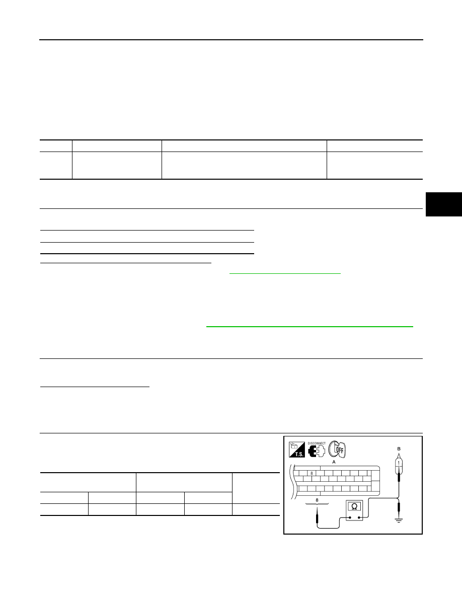
1. Check continuity between ABS actuator and electric unit (control
unit) harness connector E125 (A) terminal 8 and brake fluid level
switch harness connector E21 (B) terminal 1.
2. Check continuity between ABS actuator and electric unit (control
unit) connector E125 (A) terminal 8 and ground.
DTC
Display item
Malfunction detected condition
Possible cause
C1155
BR FLUID LEVEL LOW
Brake fluid level is low or communication line between
the ABS actuator and electric unit (control unit) and brake
fluid level switch is open or shorted.
• Harness or connector
• Brake fluid level switch
• Brake fluid level
Self-diagnosis results
BR FLUID LEVEL LOW
ABS actuator and electric unit
(control unit)
Brake fluid level switch
Continuity
Connector
Terminal
Connector
Terminal
E125 (A)
8
E21 (B)
1
Yes
AWFIA0025ZZ
BRC-64
< COMPONENT DIAGNOSIS >
[VDC/TCS/ABS]
C1155 BRAKE FLUID LEVEL SWITCH
Is the inspection result normal?
YES
>> GO TO 3
NO
>> Repair or replace malfunctioning components.
3.
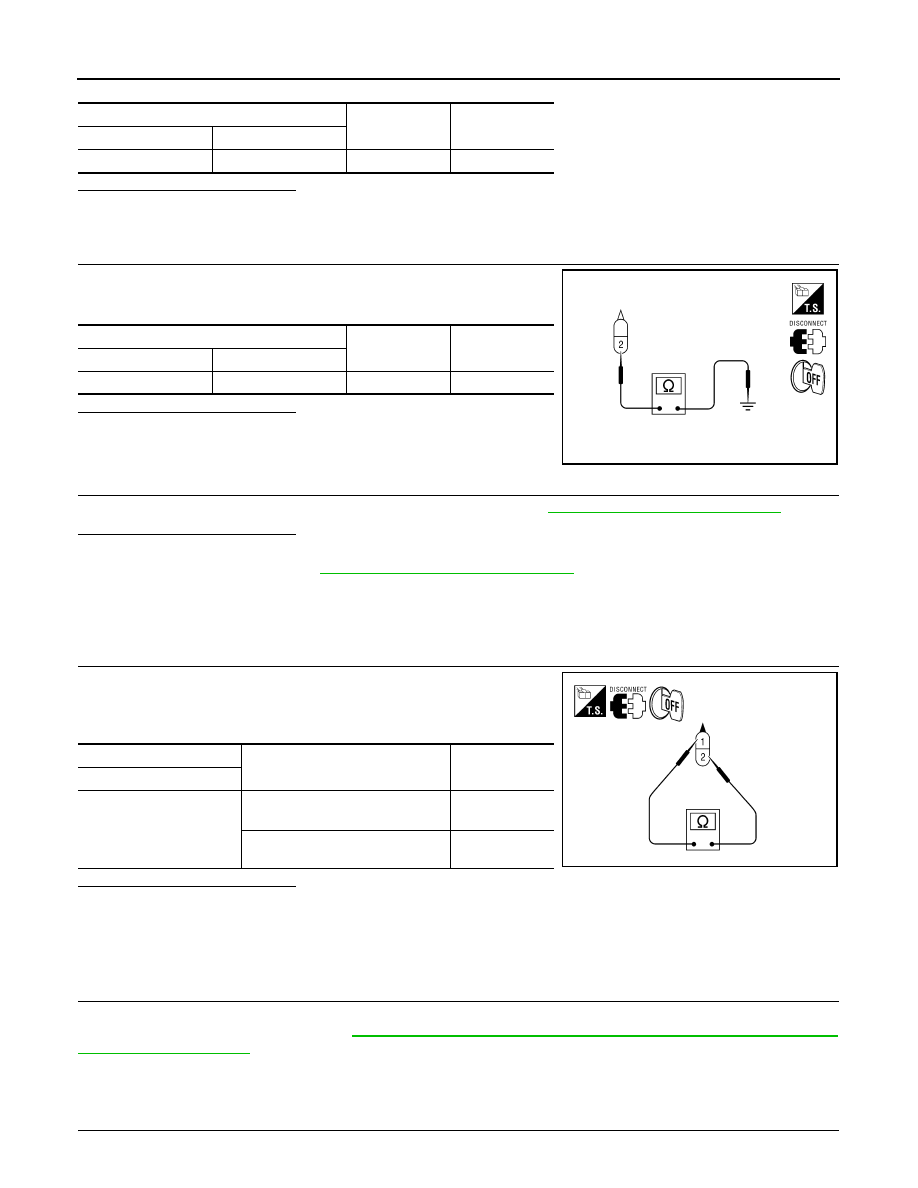
CHECK BRAKE FLUID LEVEL SWITCH GROUND
Check continuity between brake fluid level switch connector E21 ter-
minal 2 and ground.
Is the inspection result normal?
YES
>> GO TO 4
NO
>> Repair or replace malfunctioning components.
4.
CHECK BRAKE FLUID LEVEL SWITCH
Perform the brake fluid level switch component inspection. Refer to
BRC-64, "Component Inspection"
Is the inspection result normal?
YES
>> Perform self-diagnosis again. If the same results appear, replace ABS actuator and electric unit
(control unit). Refer to
BRC-116, "Removal and Installation"
.
NO
>> Replace brake fluid level switch.
Component Inspection
INFOID:0000000005148031
1.
CHECK BRAKE FLUID LEVEL SWITCH
1. Turn ignition switch OFF.
2. Disconnect brake fluid level switch connector.
3. Check continuity between brake fluid level switch terminals.
Is the inspection result normal?
YES
>> Inspection End
NO
>> Replace brake fluid level switch.
Special Repair Requirement
INFOID:0000000005194919
1.
ADJUSTMENT OF STEERING ANGLE SENSOR NEUTRAL POSITION
Always perform neutral position adjustment for the steering angle sensor when replacing the ABS actuator
and electric unit (control unit). Refer to
BRC-8, "ADJUSTMENT OF STEERING ANGLE SENSOR NEUTRAL
.
>> GO TO 2
2.
CALIBRATION OF DECEL G SENSOR
ABS actuator and electric unit (control unit)
—
Continuity
Connector
Terminal
E125 (A)
8
Ground
No
Brake fluid level switch
—
Continuity
Connector
Terminal
E21
2
Ground
Yes
AWFIA0026ZZ
Brake fluid level switch
Condition
Continuity
Terminal
1
− 2
When brake fluid is full in the reser-
voir tank.
No
When brake fluid is empty in the
reservoir tank.
Yes
ALFIA0026ZZ
Нет комментариевНе стесняйтесь поделиться с нами вашим ценным мнением.
Текст