Infiniti QX56 (JA60). Manual — part 49
AV-4
STEERING SWITCH . . . . . . . . . .
Removal and Installation . . . . . . . . . ...
REAR AUDIO REMOTE CONTROL UNIT . ..
Removal and Installation . . . . . . . . . ...
DVD ENTERTAINMENT SYSTEM . . . . ..
Removal and Installation . . . . . . . . . ...
BOSE SPEAKER AMP . . . . . . . . .
Removal and Installation . . . . . . . . . ...
AUDIO ANTENNA . . . . . . . . . . ...
Location of Antennas . . . . . . . . . . . .
Window Antenna Repair . . . . . . . . . .
SATELLITE RADIO ANTENNA . . . . . ...
Removal and Installation . . . . . . . . . ...
GPS ANTENNA . . . . . . . . . . . .
Removal and Installation . . . . . . . . . ...
MICROPHONE . . . . . . . . . . . . .
Removal and Installation . . . . . . . . . ...
REAR VIEW CAMERA . . . . . . . . . .
Removal and Installation . . . . . . . . . ...
REAR VIEW CAMERA CONTROL UNIT . . .
AV
DIAGNOSIS AND REPAIR WORKFLOW
AV-5
< BASIC INSPECTION >
[AUDIO SYSTEM]
C
D
E
F
G
H
I
J
K
L
M
B
A
O
P
BASIC INSPECTION
DIAGNOSIS AND REPAIR WORKFLOW
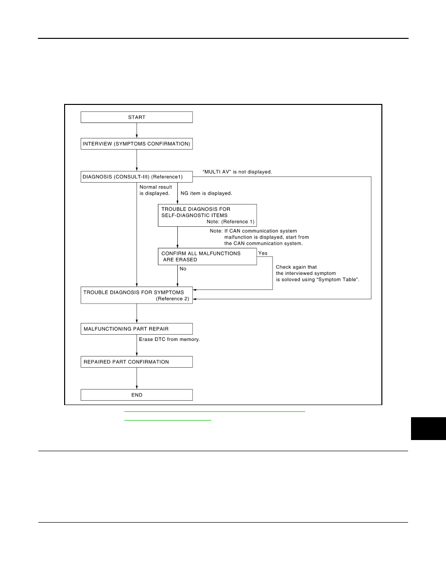
Work Flow
INFOID:0000000005146219
OVERALL SEQUENCE
• Reference 1··· Refer to
AV-38, "AV CONTROL UNIT : CONSULT-III Function"
.
• Reference 2··· Refer to
DETAILED FLOW
1.
CHECK SYMPTOM
Check the malfunction symptoms by performing the following items.
• Interview the customer to obtain the malfunction information (conditions and environment when the malfunc-
tion occurred).
• Check the symptom.
>> GO TO 2.
2.
SELF-DIAGNOSIS (CONSULT-III)
1. Connect CONSULT-III and perform “SELF-DIAGNOSIS” for “MULTI AV”.
NOTE:
Skip to step 4 of the diagnosis procedure if “MULTI AV” is not displayed.
2. Check if any DTC No. is displayed in the self-diagnosis results.
AWNIA0030GB

AV-6
< BASIC INSPECTION >
[AUDIO SYSTEM]
DIAGNOSIS AND REPAIR WORKFLOW
Is any DTC No. displayed?
YES
>> GO TO 3.
NO
>> GO TO 4.
3.
CHECK SELF-DIAGNOSIS RESULTS (CONSULT-III)
1. Check the DTC No. indicated in the self-diagnosis results.
2. Perform the relevant diagnosis referring to the DTC No. list. Refer to
NOTE:
Start with the diagnosis for the CAN communication system if “CAN COMM CIRCUIT [U1000] or CONTROL
UNIT (CAN) [U1010]” is displayed.
>> GO TO 5.
4.
PERFORM DIAGNOSIS BY SYMPTOM
Perform the relevant diagnosis referring to the diagnosis chart by symptom. Refer to
.
>> GO TO 5.
5.
REPAIR OR REPLACE MALFUNCTIONING PARTS
Repair or replace the identified malfunctioning parts.
NOTE:
Erase the stored self-diagnosis results after repairing or replacing the relevant components if any DTC No. has
been indicated in the self-diagnosis results.
>> GO TO 6.
6.
CHECK AFTER REPAIR
1. Perform self-diagnosis for “MULTI AV” with CONSULT-III after repairing or replacing the malfunctioning
parts.
2. Check if any DTC No. is displayed in the self-diagnosis results.
Is any DTC No. displayed?
YES
>> GO TO 3.
NO
>> GO TO 7.
7.
FINAL CHECK
Perform the operation check to confirm that the malfunction symptom is solved or that any other symptoms
are present.
Are any symptoms present?
YES
>> GO TO 4.
NO
>> Inspection End.
AV
INSPECTION AND ADJUSTMENT
AV-7
< BASIC INSPECTION >
[AUDIO SYSTEM]
C
D
E
F
G
H
I
J
K
L
M
B
A
O
P
INSPECTION AND ADJUSTMENT
REAR VIEW MONITOR GUIDING LINE ADJUSTMENT
REAR VIEW MONITOR GUIDING LINE ADJUSTMENT : Description
INFOID:0000000005146220
This mode is used to modify the side distance guidelines if they are dislocated from the rear view monitor
image, because of variations of body/camera mounting conditions.
REAR VIEW MONITOR GUIDING LINE ADJUSTMENT : Special Repair Requirement
INFOID:0000000005146221
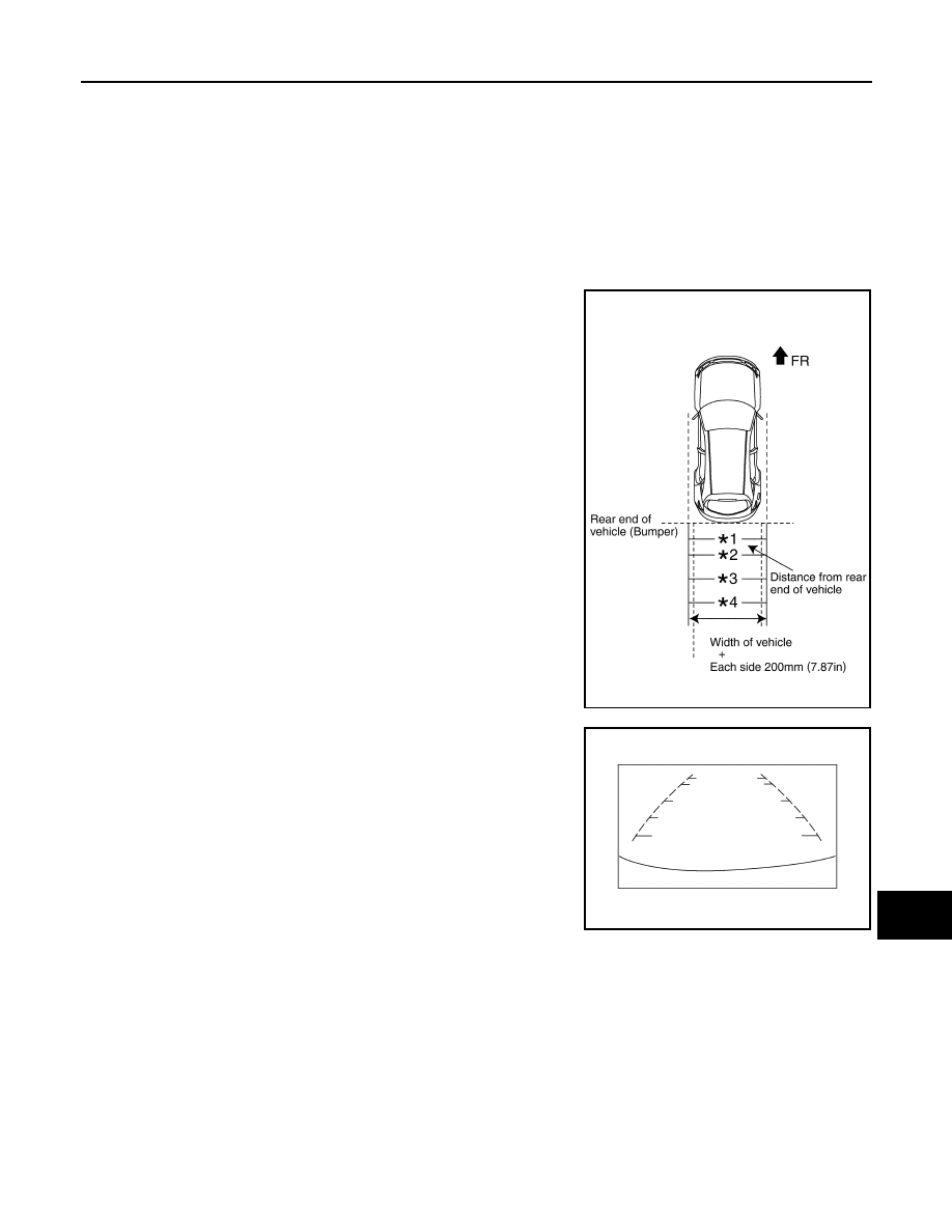
1. Create a correction line to modify the screen.
Draw lines on the rearward of the vehicle passing through the
following points: 200 mm (7.87 inch) from both sides of the vehi-
cle, and
• *1: 0.5 m (1.5 feet)
• *2: 1 m (3 feet)
• *3: 2 m (7 feet)
• *4: 3 m (10 feet)
and from the rear end of the bumper
2. With the ignition switch OFF, connect CONSULT-III, then turn
ignition switch ON. Select “REARVIEW CAMERA”.
CAUTION:
Stop engine for safety when correcting side distance guide-
line.
3. Shift the A/T selector lever to R position.
4. Touch “SELCT GUIDELINE PATTERN” under “WORK SUPPORT” menu.
5. Touch “UP” or “DOWN”, and select the guide line, “PATTERN NO. 0” or “PATTERN NO. 1”, which is the
closest to the corrected line.
6. Touch “SAVE”, and confirm the guide line.
7. Touch “END”.
8. Touch “ADJ GUIDELINE POSITION” under the “WORK SUPPORT” menu.
9. Adjust the guide line touching “X UP”, “X DOWN”, “Y UP” or “Y DOWN” so that the corrected line can fit
the guide line.
10. Touch “SAVE”, and confirm the guide line.
SKIA5637E
SKIA6103E
Нет комментариевНе стесняйтесь поделиться с нами вашим ценным мнением.
Текст