Infiniti QX56 (JA60). Manual — part 568
GI-46
< BASIC INSPECTION >
CONSULT-III CHECKING SYSTEM
CONSULT-III CHECKING SYSTEM
Description
INFOID:0000000005149609
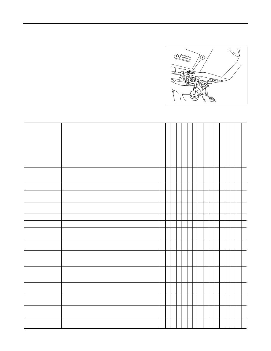
• When CONSULT-III is connected with a data link connector
equipped on the vehicle side, it will communicate with the control
unit equipped in the vehicle and then enable various kinds of diag-
nostic tests.
• Refer to “CONSULT-III Operation Manual” for more information.
Function and System Application
INFOID:0000000005149610
1
: Hood release handle
2
: Data link connector
ALBIA0047ZZ
Diagnostic test
mode
Function
ENGINE
T
R
ANSMI
SSION
ICC
*1
AB
S
AI
R BAG
IPDM
E/R
BCM
METER/
M&A
INTELLI
G
E
N
T
KEY
AUT
O
DRIVE
POS.
REAR
V
IEW CA
MERA
AIR LEVELIZER
MUL
TI
A
V
ALL MODE
A
W
D/4WD
*2
HV
A
C
SONAR
*3
Work support
This mode enables a technician to adjust some devices
faster and more accurately by following the indications on
CONSULT-III.
x - x x - - x - x x x x - x - -
Self-diagnostic
Self-diagnostic can be performed quickly.
- -
-
- x - - - - - - - -
-
- -
Self-diagnostic re-
sults
Self-diagnostic results can be read and erased quickly.
x x x x - x x x x x - x x x x x
Trouble diagnostic
record
Current self-diagnostic results and all trouble diagnostic
records previously stored can be read.
- -
- - x - - - - - - - -
-
- -
Data monitor
Input/Output data in the ECM can be read.
x x x x - x - x x x x x x x x x
Data monitor (spec)
Data monitor specification can be read.
x -
-
- - - - - - - - - -
-
- -
CAN diagnosis
The condition of CAN communication can be indicated by
a topology.
x x x x x x x x x x - - x x x -
CAN diagnosis sup-
port monitor
The communication condition of CAN communication line
can be read.
x x x x - x x x x x - - x x x -
Active test
Diagnostic Test Mode in which CONSULT-III drives some
actuators apart from the ECMs and also shifts some pa-
rameters in a specified range.
x - x x - x - - x x - x -
-
- -
Function test
This mode can show results of self-diagnosis of ECU with
either “OK” or “NG”. For engines, more practical tests re-
garding sensors/switches and/or actuators are available.
x x x x x - - - x - - - -
-
- -
DTC & SRT confir-
mation
The results of SRT (System Readiness Test) and the self-
diagnosis status/result can be confirmed.
x - x - - - - - x - - - -
-
- -
DTC work support
The operating condition to confirm Diagnosis Trouble
Codes can be selected.
x x x - - - - - x - - - -
-
- -
ECM/ECU part num-
ber
ECM/ECU part number can be read.
x x x x - - x - x x x x x x x x
ECU discriminated
No.
Classification number of a replacement ECU can be read
to prevent an incorrect ECU from being installed.
- -
-
- x - - - - - - - -
-
- -
CONSULT-III CHECKING SYSTEM
GI-47
< BASIC INSPECTION >
C
D
E
F
G
H
I
J
K
L
M
B
GI
N
O
P
x : Applicable
*1: With intelligent cruise control
*2: With 4-wheel drive
*3: With front and rear sonar system
*4: With security card installed
CONSULT-III Data Link Connector (DLC) Circuit
INFOID:0000000005149611
INSPECTION PROCEDURE
If the CONSULT-III cannot diagnose the system properly, check the following items.
NOTE:
The CAN and DDL2 circuits from DLC pins 6, 7 and 14 may be connected to more than one system. A short in
any circuit connected to a control unit in one system may affect CONSULT-III access to other systems.
Passenger Airbag
Displays the STATUS (readiness) of the front passenger
air bag.
- -
-
- x - - - - - - - -
-
- -
AV COMM monitor
The condition of AV communication can be indicated.
- -
-
- - - - - - - - - x -
- -
Configuration
Sets control module parameters to match vehicle options. - -
-
- - - x - - - - - -
-
- -
PIN read
*4
This mode shows the BCM-specific 5-digit code.
- -
-
- - - x - - - - - -
-
- -
Control unit
initialization
*4
All registered ignition key IDs in NATS components can be
initialized and new IDs can be registered.
- -
-
- - - x - - - - - -
-
- -
Diagnostic test
mode
Function
ENGINE
TRANSMISS
ION
ICC
*1
ABS
AIR B
A
G
IPDM E/R
BC
M
MET
E
R/M
&
A
INTELLIGENT KEY
AUT
O
DRIVE
POS.
R
E
AR
VI
EW CAMERA
AIR LEVELI
Z
ER
MUL
T
I A
V
ALL MODE A
W
D/4WD
*2
HV
AC
SONAR
*3
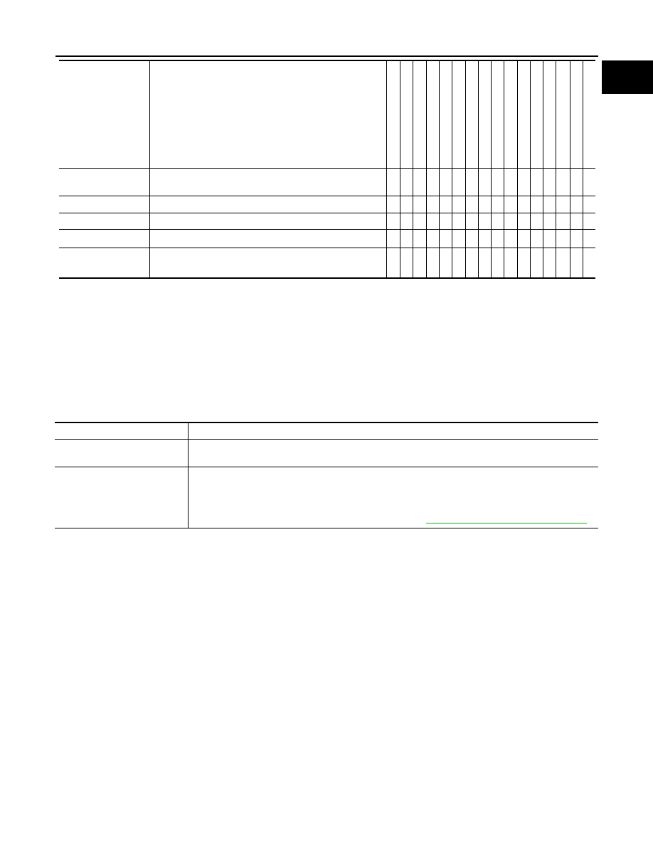
Symptom
Check item
CONSULT-III cannot access
any system.
• CONSULT-III DLC power supply circuit (Terminal 8) and ground circuit (Terminal 4)
CONSULT-III cannot access in-
dividual system. (Other sys-
tems can be accessed.)
• Power supply and ground circuit for the control unit of the system (For detailed circuit, refer to wiring
diagram for each system.)
• Open or short circuit between the system and CONSULT-III DLC (For detailed circuit, refer to wiring
diagram for each system.)
• Open or short circuit CAN communication line. Refer to
GI-48
< BASIC INSPECTION >
CONSULT-III CHECKING SYSTEM
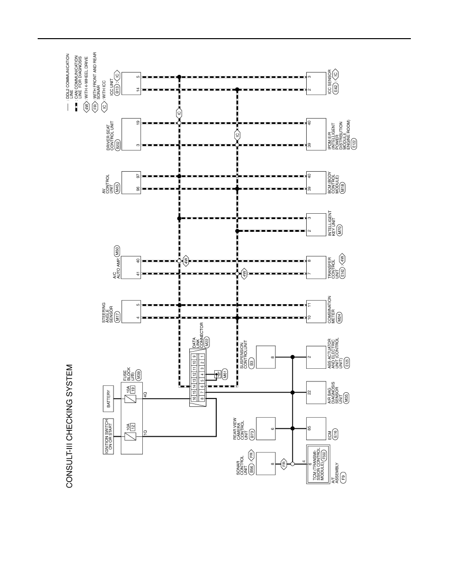
Wiring Diagram
INFOID:0000000005149612
ABAWA0027GB
GW-1
BODY EXTERIOR, DOORS, ROOF & VEHICLE SECURITY
C
D
E
F
G
H
I
J
L
M
SECTION
GW
A
B
GW
N
O
P
CONTENTS
GLASS & WINDOW SYSTEM
SYMPTOM DIAGNOSIS . . . . . . . ...
SQUEAK AND RATTLE TROUBLE DIAGNO-
SIS . . . . . . . . . . . . . . . . . ...
Work Flow . . . . . . . . . . . . . . . .....
Generic Squeak and Rattle Troubleshooting . . ....
Diagnostic Worksheet . . . . . . . . . . . ...
PRECAUTION . . . . . . . . . . . ...
PRECAUTIONS . . . . . . . . . . . . ...
Precaution Necessary for Steering Wheel Rota-
tion After Battery Disconnect . . . . . . . . .....
Handling for Adhesive and Primer . . . . . . ....
PREPARATION . . . . . . . . . . ...
PREPARATION . . . . . . . . . . . . .
Special Service Tool . . . . . . . . . . . .
Commercial Service Tool . . . . . . . . . .
ON-VEHICLE REPAIR . . . . . . . . .
WINDSHIELD GLASS . . . . . . . . . ...
Removal and Installation . . . . . . . . . . .
REAR WINDOW GLASS AND MOLDING . .
Removal and Installation . . . . . . . . . . .
FRONT DOOR GLASS AND REGULATOR . .
Removal and Installation . . . . . . . . . . .
REAR DOOR GLASS AND REGULATOR . ...
Removal and Installation . . . . . . . . . . .
SIDE WINDOW GLASS . . . . . . . . .
Нет комментариевНе стесняйтесь поделиться с нами вашим ценным мнением.
Текст