Infiniti QX56 (JA60). Manual — part 989
TM-258
< DISASSEMBLY AND ASSEMBLY >
ASSEMBLY
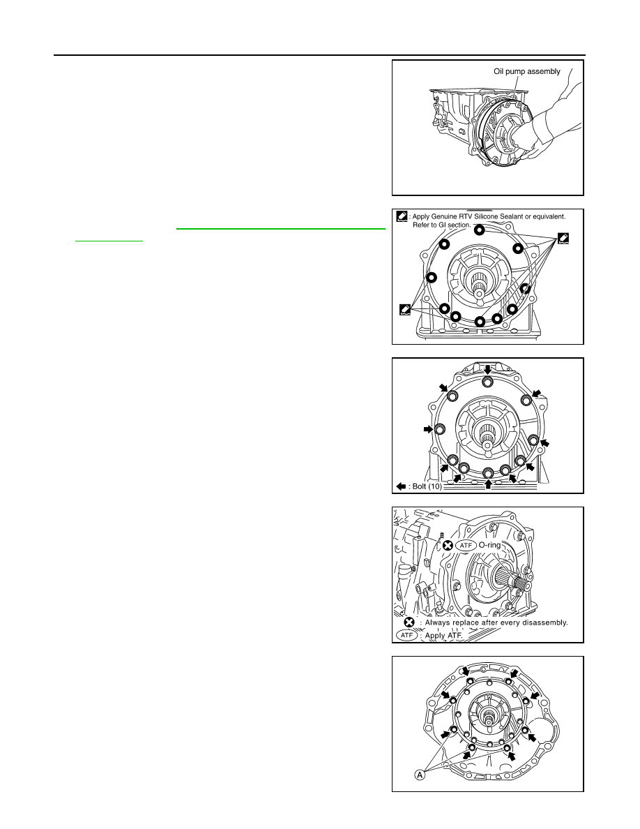
3. Install oil pump assembly in transmission case.
CAUTION:
Apply ATF to oil pump bearing.
4. Apply recommended sealant (Genuine RTV Silicone Sealant or
equivalent. Refer to
GI-15, "Recommended Chemical Products
.) to oil pump assembly as shown.
CAUTION:
Completely remove all moisture, oil, old sealant and any
foreign material from the oil pump bolts and oil pump bolt
mating surfaces.
5. Tighten oil pump bolts to specified torque.
CAUTION:
Apply ATF to oil pump bushing.
6. Install O-ring to input clutch assembly.
CAUTION:
• Do not reuse O-ring.
• Apply ATF to O-ring.
7. Install converter housing to transmission case and tighten bolts
to specified torque.
CAUTION:
Do not reuse self-sealing bolt (A).
SCIA2811E
SCIA5321E
Oil pump bolts
: 48 N·m (4.9 kg-m, 35 ft-lb)
SCIA2300E
SCIA5011E
Converter housing bolt
: 52 N·m (5.3 kg-m, 38 ft-lb)
Self-sealing bolt (A)
: 61 N·m (6.2 kg-m, 45 ft-lb)
WCIA0662E
ASSEMBLY
TM-259
< DISASSEMBLY AND ASSEMBLY >
C
E
F
G
H
I
J
K
L
M
A
B
TM
N
O
P
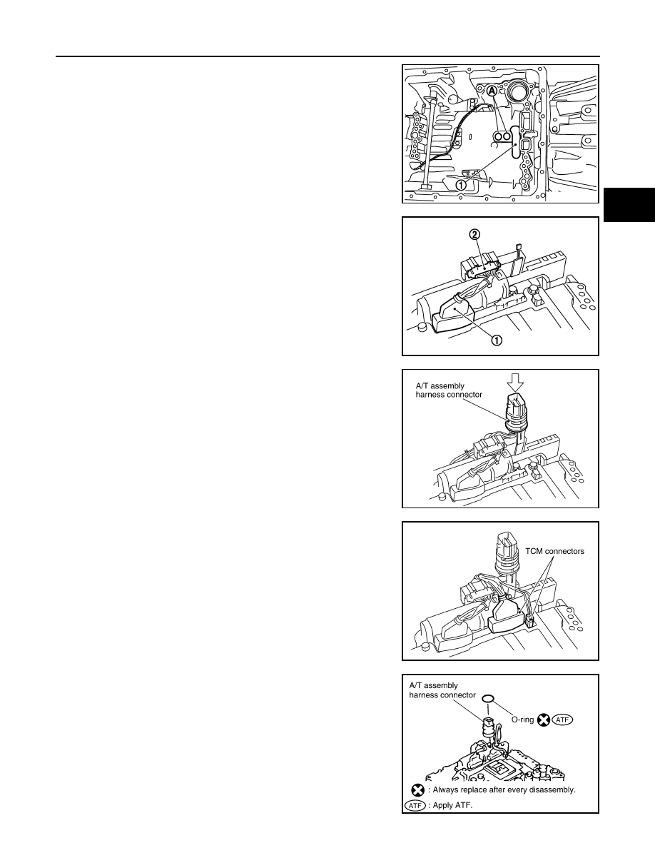
8. Make sure that brake band (1) does not close input speed sen-
sor hole (A).
9. Connect TCM connector (1) and transmission range switch con-
nector (2).
10. Install A/T assembly harness connector to control valve with
TCM..
11. Connect TCM connectors.
12. Install O-ring to A/T assembly harness connector..
CAUTION:
• Do not reuse O-ring.
• Apply ATF to O-ring.
JSDIA1318ZZ
JSDIA1317ZZ
SCIA5450E
SCIA5447E
SCIA5155E
TM-260
< DISASSEMBLY AND ASSEMBLY >
ASSEMBLY
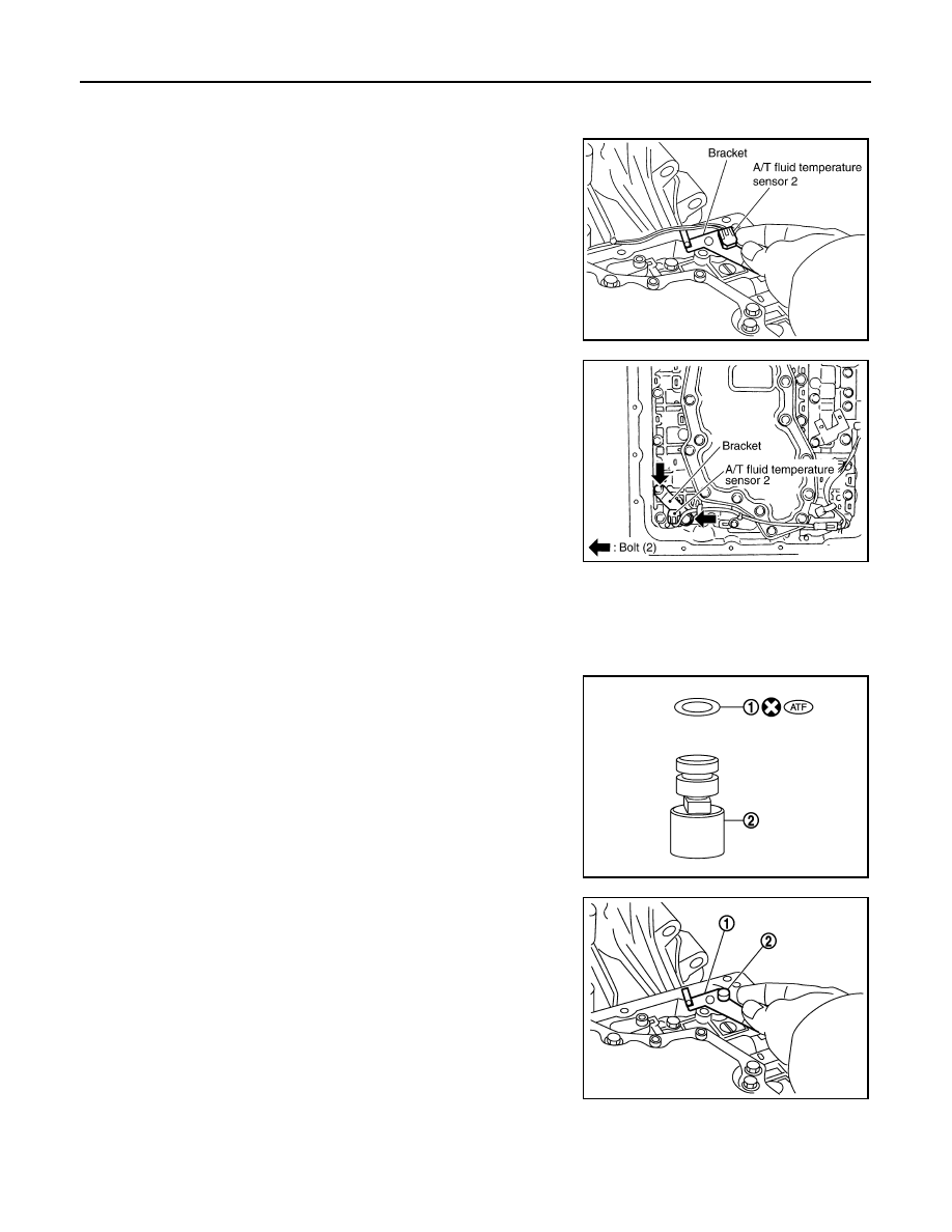
13. Install the A/T fluid temperature sensor 2 or plug as shown below.
a. A/T fluid temperature sensor 2
i.
Install A/T fluid temperature sensor 2 to bracket.
ii.
Install A/T fluid temperature sensor 2 (with bracket) to control
valve with TCM and tighten bolt to specified torque.
CAUTION:
Adjust bolt hole of bracket to bolt hole of control valve.
b. Plug
NOTE:
• When replacing the A/T fluid temperature sensor 2 with the plug, the A/T fluid temperature sensor 2 con-
nector should not be connected.
• Fold the terminal clips.
i.
Install new O-ring (1) in plug (2).
CAUTION:
• Do not reuse O-ring.
• Apply ATF to O-ring.
• O-ring should be free of contamination.
ii.
Install plug (2) to bracket (1).
SCIA5264E
Bracket bolt
: 7.9 N·m (0.81 kg-m, 70 in-lb)
SCIA5253E
JSDIA1313ZZ
JSDIA1312ZZ
ASSEMBLY
TM-261
< DISASSEMBLY AND ASSEMBLY >
C
E
F
G
H
I
J
K
L
M
A
B
TM
N
O
P
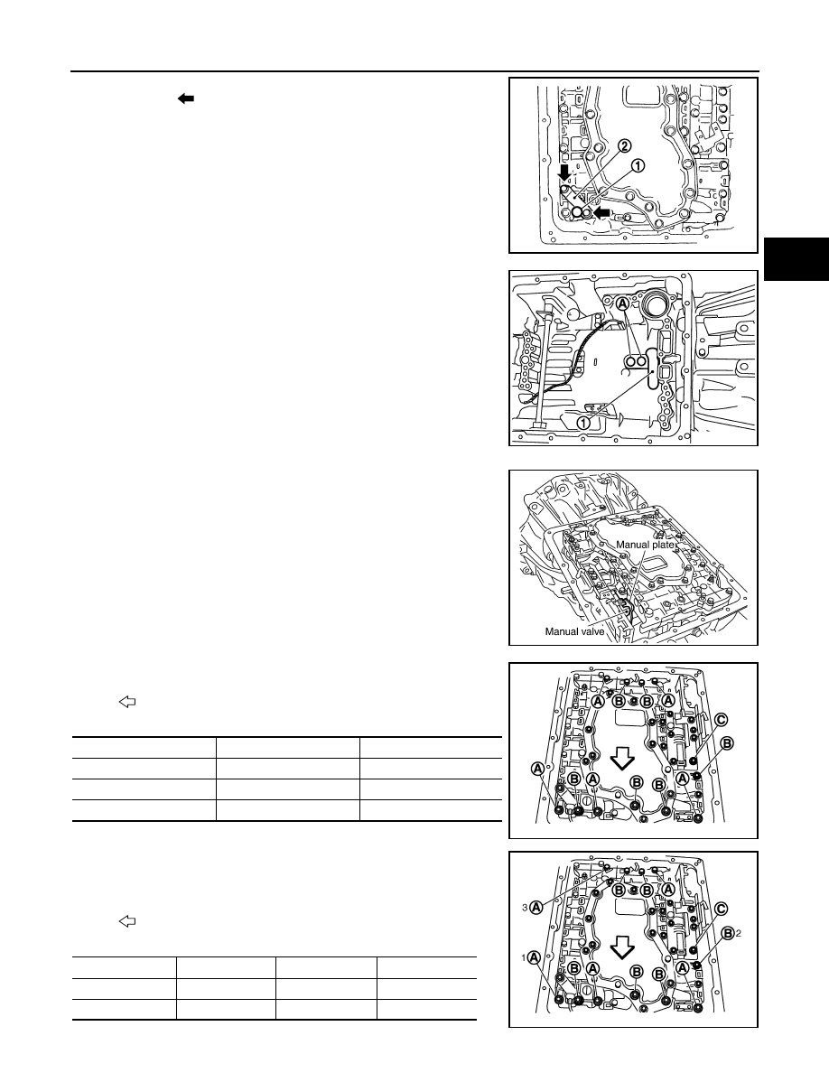
iii. Install plug (1) [with bracket (2)] to control valve with TCM and
tighten bolt (
) to specified torque.
CAUTION:
Adjust bolt hole of bracket to bolt hole of control valve.
14. Install control valve with TCM in transmission case.
CAUTION:
• Make sure that input speed sensor is securely installed
into input speed sensor hole (A).
• Hang down output speed sensor harness toward outside
so as not to disturb installation of control valve with TCM.
• Adjust A/T assembly harness connector of control valve
with TCM to terminal hole of transmission case.
• Assemble it so that manual valve cutout is engaged with
manual plate projection.
15. Install bolts (A), (B) and (C) to control valve with TCM.
16. Tighten bolt (A), (B) and (C) temporarily to prevent dislocation.
After that tighten them in order (A
→ B → C), and then tighten
other bolts.
Bracket bolt
: 7.9 N·m (0.81 kg-m, 70 in-lb)
JSDIA1311ZZ
1
: Brake band
JSDIA1318ZZ
SCIA5035E
: Front
Bolt symbol
Length mm (in)
Number of bolts
A
42 (1.65)
5
B
55 (2.17)
6
C
40 (1.57)
1
SCIA8077E
: Front
Bolt symbol
A
B
C
Number of bolts
5
6
1
Length mm (in)
42 (1.65)
55 (2.17)
40 (1.57)
SCIA8078E
Нет комментариевНе стесняйтесь поделиться с нами вашим ценным мнением.
Текст