Infiniti QX56 (JA60). Manual — part 1020
WT-8
< FUNCTION DIAGNOSIS >
TPMS
FUNCTION DIAGNOSIS
TPMS
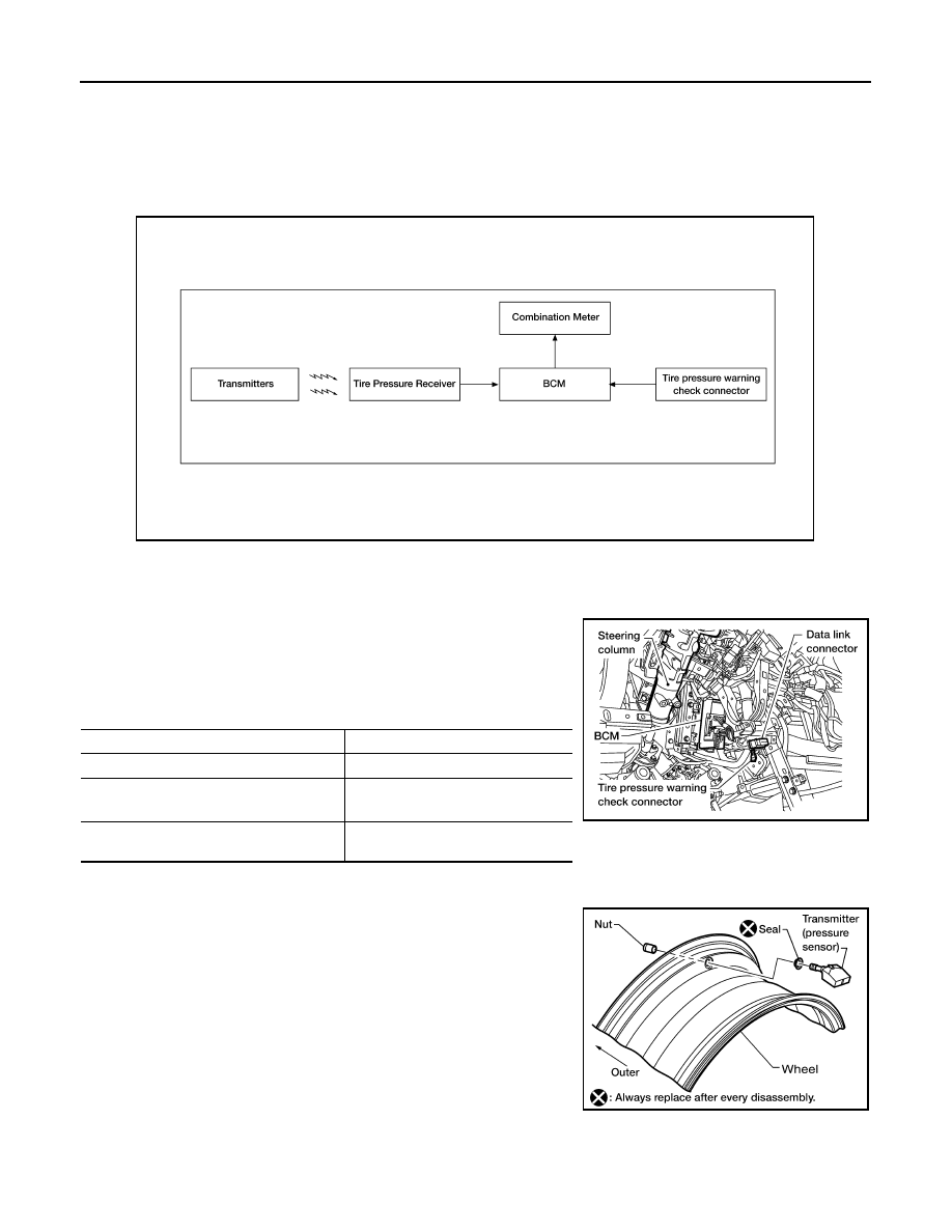
System Diagram
INFOID:0000000005148206
System Description
INFOID:0000000005148207
BODY CONTROL MODULE (BCM)
The BCM is shown with the lower instrument panel LH removed. The
BCM reads the air pressure signal received by the remote keyless
entry receiver, and controls the low tire pressure warning lamp as
shown below. It also has a self-diagnosis function to detect a system
malfunction.
TRANSMITTER
A sensor-transmitter integrated with a valve is installed in each
wheel, and transmits a detected air pressure signal in the form of a
radio wave. The radio signal is received by the remote keyless entry
receiver.
REMOTE KEYLESS ENTRY RECEIVER
ALEIA0004GB
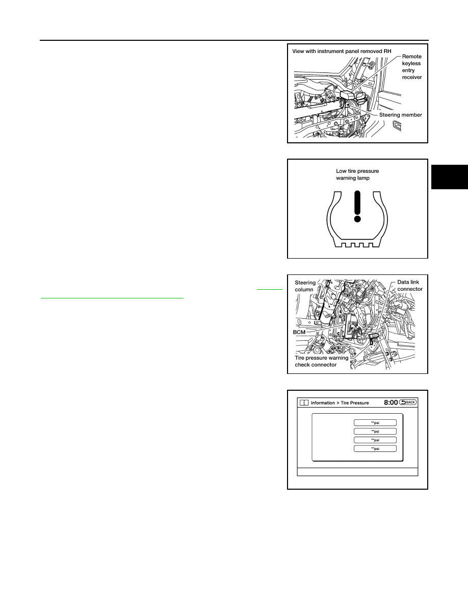
Condition
Low tire pressure warning lamp
System normal
On for 1 second after ignition ON
Tire less than 193 kPa (2.0 kg/cm
2
, 28 psi)
[Flat tire]
ON
TPMS malfunction
After key ON, flashes once per sec-
ond for 1 minute, then stays ON
LEIA0068E
WEIA0137E
TPMS
WT-9
< FUNCTION DIAGNOSIS >
C
D
F
G
H
I
J
K
L
M
A
B
WT
N
O
P
The remote keyless entry receiver is shown with the instrument
panel RH removed. The remote keyless entry receiver receives the
air pressure signal transmitted by the transmitter in each wheel.
COMBINATION METER
The combination meter receives tire pressure status from the BCM
using CAN communication. When a low tire pressure condition is
sensed by the BCM, the combination meter low tire pressure warn-
ing lamp is activated.
TIRE PRESSURE WARNING CHECK CONNECTOR
The tire pressure warning check connector can be grounded in order
to initiate self-diagnosis without a CONSULT-III. Refer to
"Self-Diagnosis (Without CONSULT-III)"
. The tire pressure warning
check connector is located behind the lower portion of the instrument
panel LH.
DISPLAY UNIT
Displays the air pressure of each tire.
NOTE:
After the ignition switch is turned on, the pressure values will not be
displayed until the data of each wheel is received.
LEIA0069E
LEIA0055E
LEIA0068E
AWEIA0017GB
WT-10
< FUNCTION DIAGNOSIS >
TPMS
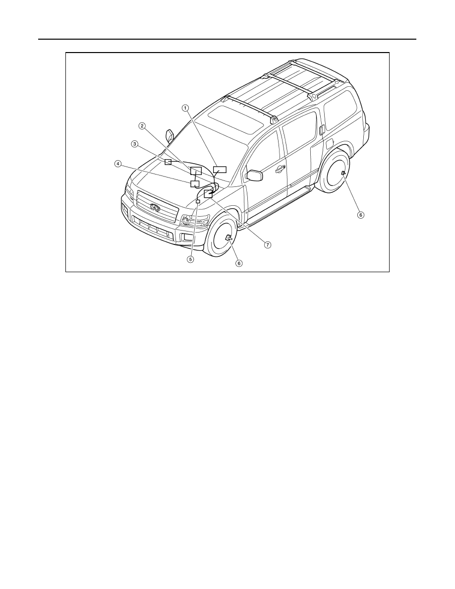
System Component
INFOID:0000000005148208
AWEIA0126ZZ
1.
Combination meter M23, M24
2.
Display unit M93
3.
Remote keyless entry receiver
M120
4.
AV control unit M43, M45
5.
Tire pressure warning check connector
M123
6.
Transmitter
7.
BCM M18, M20

DIAGNOSIS SYSTEM (BCM)
WT-11
< FUNCTION DIAGNOSIS >
C
D
F
G
H
I
J
K
L
M
A
B
WT
N
O
P
DIAGNOSIS SYSTEM (BCM)
CONSULT-III Function (BCM)
INFOID:0000000005148209
CONSULT-III DIAGNOSTIC MODES
CONSULT-III can display each diagnostic item using the diagnostic test modes shown following.
DESCRIPTION
During driving, the tire pressure monitoring system receives the signal transmitted from the transmitter
installed in each wheel, and turns on the low tire pressure warning lamp when the tire pressure becomes low.
The control unit (BCM) for this system has pressure judgement and self-diagnosis functions.
FUNCTION
When the tire pressure monitoring system detects low inflation pressure or an internal malfunction, the low tire
pressure warning lamp in the combination meter comes on. The malfunction is indicated by the low tire pres-
sure warning lamp flashing.
CONSULT-III Application to Tire Pressure Monitoring System
× : Applicable
– : Not applicable
Data Monitor Mode
Diagnostic mode
Description
Work Support
Supports inspections and adjustments. Commands are transmitted to the BCM
for setting the status suitable for required operation, input/output signals are re-
ceived from the BCM and received data is displayed.
Data Monitor
Displays BCM input/output data in real time.
Active Test
Operation of electrical loads can be checked by sending drive signal to them.
Self Diagnostic Result
Displays BCM self-diagnosis results.
CAN Diag Support Monitor
The result of transmit/receive diagnosis of CAN communication can be read.
ECU Identification
BCM part number can be read.
Configuration
Performs BCM configuration read/write functions.
ITEM
SELF-DIAGNOSTIC RESULTS
DATA MONITOR
Front - Left transmitter
×
×
Front - Right transmitter
×
×
Rear - Left transmitter
×
×
Rear - Right transmitter
×
×
Warning lamp
—
×
Vehicle speed
×
×
CAN Communication
×
×
MONITOR
CONDITION
SPECIFICATION
VEHICLE SPEED
Drive vehicle.
Vehicle speed (km/h or MPH)
AIR PRESS FL
• Drive vehicle for a few minutes.
or
• Ignition switch ON and activation tool
is transmitting activation signals.
Tire pressure (kPa or psi)
AIR PRESS FR
AIR PRESS RR
AIR PRESS RL
ID REGST FL1
Ignition switch ON
ID not registered: YET
ID registered: DONE
ID REGST FR1
ID REGST RR1
ID REGST RL1
Нет комментариевНе стесняйтесь поделиться с нами вашим ценным мнением.
Текст