Infiniti QX56 (JA60). Manual — part 719
PB-10
< ON-VEHICLE REPAIR >
PARKING BRAKE SHOE
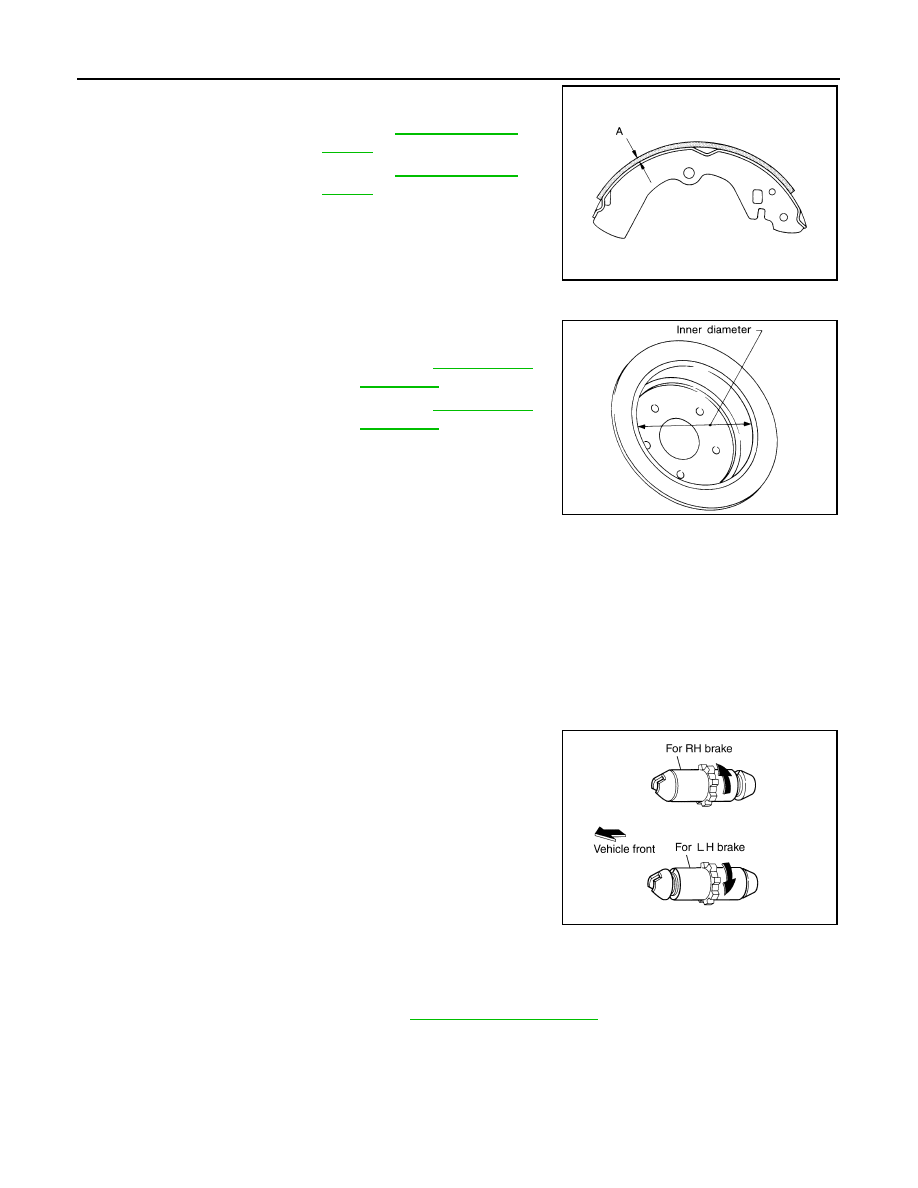
• Check thickness of lining.
Disc Rotor Inner Diameter Inspection
• Check inner diameter inside drum area of disc rotor.
Other Inspections
• Check shoe sliding surface on back plate for excessive wear and damage.
• Check anti-rattle pins for excessive wear and corrosion.
• Check return springs for sagging.
• Check adjuster for rough operation.
• When disassembling adjuster, apply PBC (Poly Butyl Cuprysil) grease or equivalent to the threads.
• Check either visually or with a vernier caliper to see if there is any excessive wear, cracks, or damage inside
drum area of disc rotor.
INSTALLATION
Installation is in the reverse order of removal.
• Apply brake grease to the specified points during assembly.
• Assemble adjuster so that threaded part expands when rotating it
in the direction shown by the arrow.
• Shorten adjuster by rotating it.
NOTE:
After replacing brake shoes or disc rotors, or if brakes do not function well, perform break-in operation as fol-
lows.
1. Adjust parking brake pedal stroke. Refer to
.
2. Perform parking brake break-in operation by driving the vehicle forward under the following conditions:
• Vehicle speed at 40 km/h (25 MPH)
• Apply parking brake with an operating force of 196 N (20.0 kg-f, 44.1 lb-f) set
• Apply parking brake for a period of 30 seconds
CAUTION:
• To prevent lining from getting too hot, allow a cool off period of approximately 5 minutes after
every break-in operation.
Standard thickness (A)
: Refer to
Wear limit thickness (A) : Refer to
SBR021A
Standard inner diameter
Wear limit of inner diameter
SBR768A
SFIA0153E
PARKING BRAKE SHOE
PB-11
< ON-VEHICLE REPAIR >
C
D
E
G
H
I
J
K
L
M
A
B
PB
N
O
P
• Do not perform excessive break-in operations, because it may cause uneven or early wear of lin-
ing.
3. After break-in operation, check pedal stroke of parking brake. Readjust if it is no longer at the specified
stroke. Refer to

PB-12
< SERVICE DATA AND SPECIFICATIONS (SDS)
SERVICE DATA AND SPECIFICATIONS (SDS)
SERVICE DATA AND SPECIFICATIONS (SDS)
SERVICE DATA AND SPECIFICATIONS (SDS)
Parking Brake
INFOID:0000000005147936
Unit: mm (in)
Parking Brake Control
INFOID:0000000005147937
Type
Disc rotor with inner drum
Brake lining
Standard thickness (new)
3.79
± 0.21 (0.149 ± 0.008)
Wear limit thickness
0.5 (0.020)
Drum inner diameter (disc)
Standard inner diameter (new)
205
± 0.13 (8.07 ± 0.01)
Wear limit of inner diameter
205.7 (8.10)
Control type
Foot pedal
Number of notches [under force of 196 N (20.0 kg-f, 44.1 lb-f)]
3 – 4 notches
Number of notches when warning lamp switch comes on
1 notch
PCS
PCS-1
ELECTRICAL & POWER CONTROL
C
D
E
F
G
H
I
J
K
L
B
SECTION
PCS
A
O
P
N
CONTENTS
POWER CONTROL SYSTEM
IPDM E/R
BASIC INSPECTION . . . . . . . . .
DIAGNOSIS AND REPAIR WORKFLOW . . ..
Work Flow . . . . . . . . . . . . . . . .....
FUNCTION DIAGNOSIS . . . . . . . ...
RELAY CONTROL SYSTEM . . . . . . . ..
System Diagram . . . . . . . . . . . . . ....
System Description . . . . . . . . . . . . ...
Component Parts Location . . . . . . . . . ....
POWER CONTROL SYSTEM . . . . . . . .
System Diagram . . . . . . . . . . . . . ....
System Description . . . . . . . . . . . . ...
SIGNAL BUFFER SYSTEM . . . . . . . .
System Diagram . . . . . . . . . . . . . ....
System Description . . . . . . . . . . . . ...
POWER CONSUMPTION CONTROL SYS-
TEM . . . . . . . . . . . . . . . . .
System Diagram . . . . . . . . . . . . . ..
System Description . . . . . . . . . . . . .
Component Parts Location . . . . . . . . . ..
DIAGNOSIS SYSTEM (IPDM E/R) . . . . . .
Diagnosis Description . . . . . . . . . . . .
CONSULT - III Function (IPDM E/R) . . . . . ...
COMPONENT DIAGNOSIS . . . . . . .
U1000 CAN COMM CIRCUIT . . . . . . ...
Description . . . . . . . . . . . . . . . ...
DTC Logic . . . . . . . . . . . . . . . .
Diagnosis Procedure . . . . . . . . . . . ...
POWER SUPPLY AND GROUND CIRCUIT .
Diagnosis Procedure . . . . . . . . . . . ...
ECU DIAGNOSIS . . . . . . . . . . .
IPDM E/R (INTELLIGENT POWER DISTRI-
BUTION MODULE ENGINE ROOM) . . . .
Reference Value . . . . . . . . . . . . . ..
Terminal Layout . . . . . . . . . . . . . ...
Physical Values . . . . . . . . . . . . . ...
Wiring Diagram . . . . . . . . . . . . . .
Fail Safe . . . . . . . . . . . . . . . . ..
DTC Index . . . . . . . . . . . . . . . ...
PRECAUTION . . . . . . . . . . . ..
PRECAUTIONS . . . . . . . . . . . . .
Precaution Necessary for Steering Wheel Rota-
tion After Battery Disconnect . . . . . . . . ...
REMOVAL AND INSTALLATION . . . ...
IPDM E/R (INTELLIGENT POWER DISTRI-
BUTION MODULE ENGINE ROOM) . . . .
Нет комментариевНе стесняйтесь поделиться с нами вашим ценным мнением.
Текст