Infiniti QX56 (JA60). Manual — part 711
MWI
IPDM E/R (INTELLIGENT POWER DISTRIBUTION MODULE ENGINE ROOM)
MWI-79
< ECU DIAGNOSIS >
C
D
E
F
G
H
I
J
K
L
M
B
A
O
P
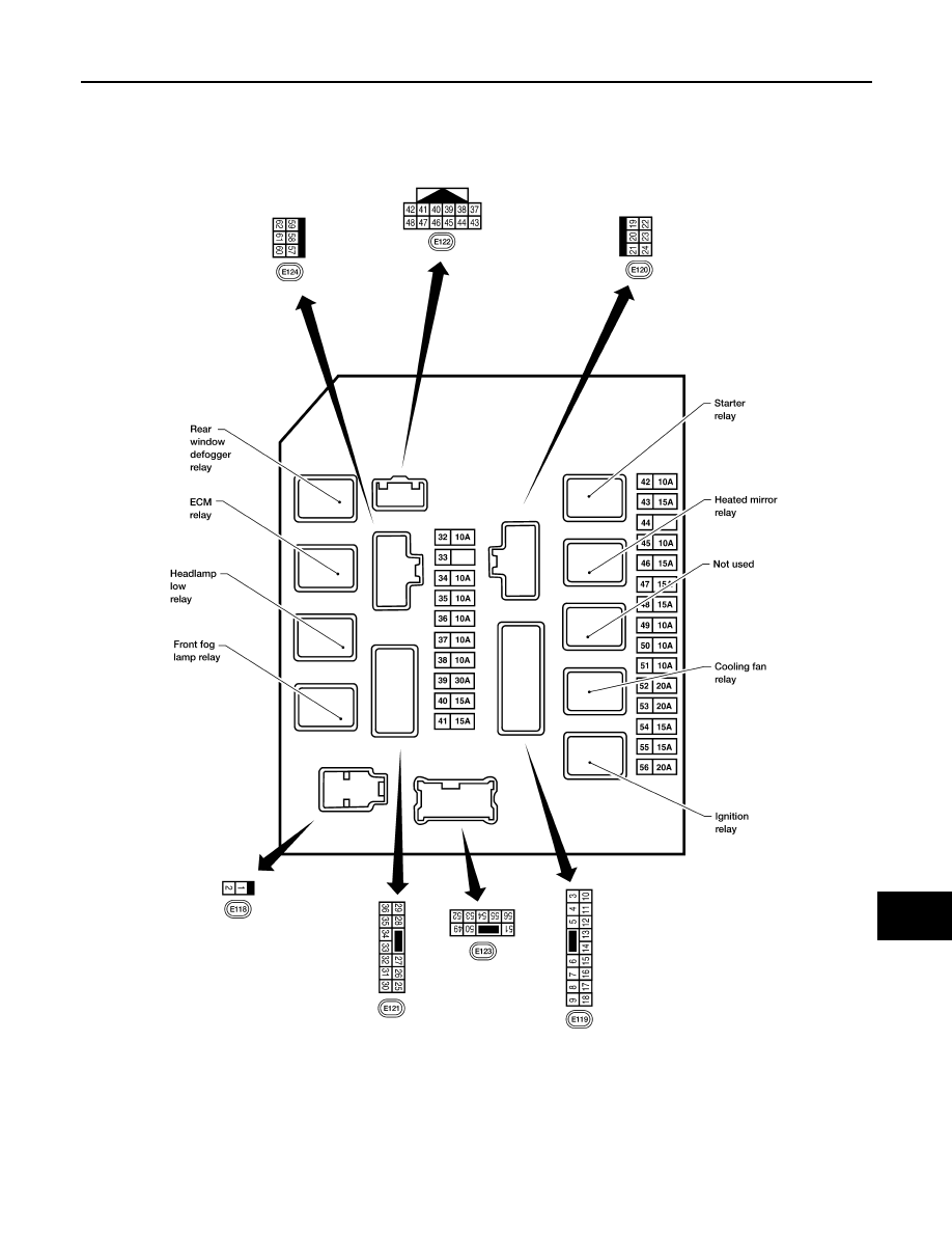
Terminal Layout
INFOID:0000000005380665
TERMINAL LAYOUT —TYPE A
WKIA5852E
MWI-80
< ECU DIAGNOSIS >
IPDM E/R (INTELLIGENT POWER DISTRIBUTION MODULE ENGINE ROOM)
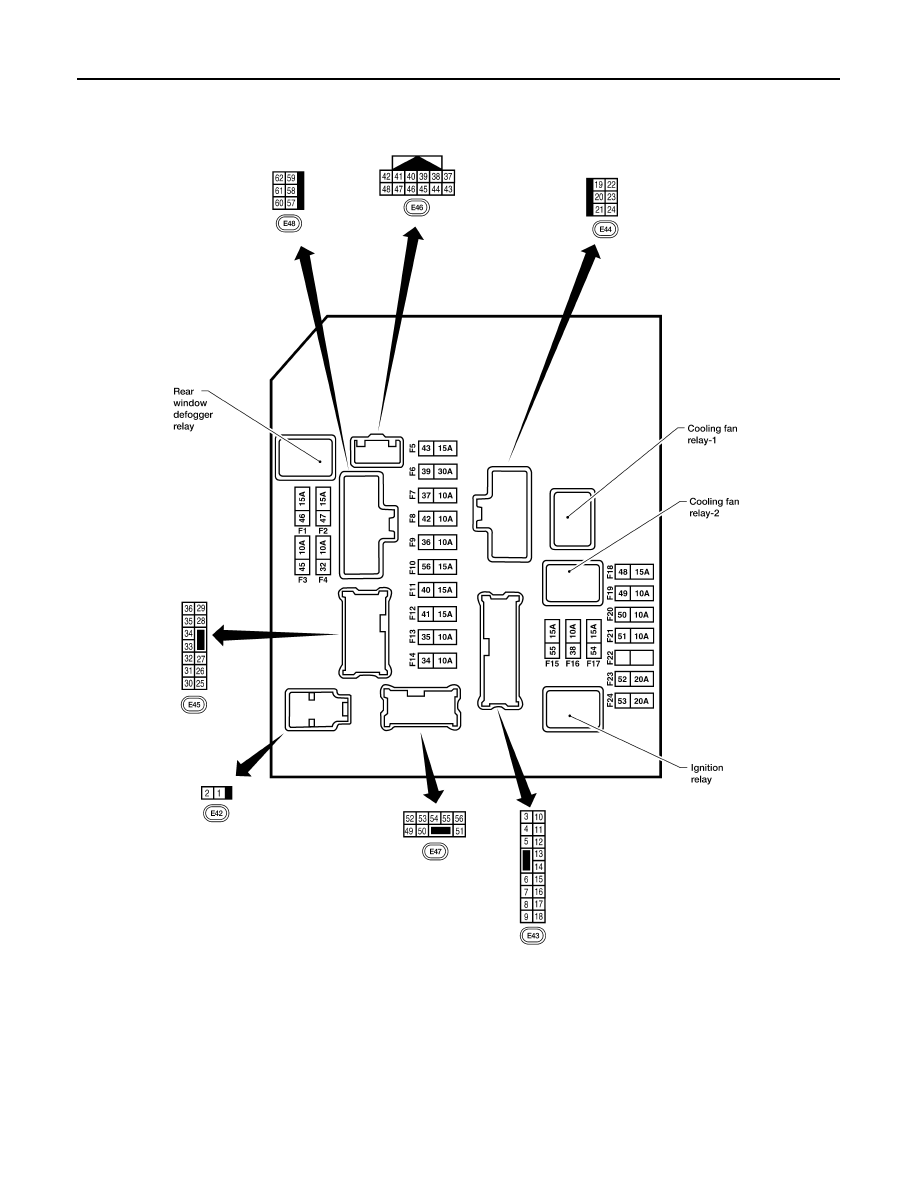
TERMINAL LAYOUT —TYPE B
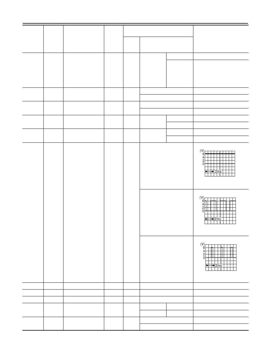
Physical Values
INFOID:0000000005380666
PHYSICAL VALUES
AAMIA0364GB

MWI
IPDM E/R (INTELLIGENT POWER DISTRIBUTION MODULE ENGINE ROOM)
MWI-81
< ECU DIAGNOSIS >
C
D
E
F
G
H
I
J
K
L
M
B
A
O
P
Terminal
Wire
color
Signal name
Signal
input/
output
Measuring condition
Reference value
(Approx.)
Igni-
tion
switch
Operation or condition
1
B/Y
Battery power supply
Input
OFF
—
Battery voltage
2
R
Battery power supply
Input
OFF
—
Battery voltage
3
BR
ECM relay
Output
—
Ignition switch ON or START
Battery voltage
Ignition switch OFF or ACC
0V
4
W/L
ECM relay
Output
—
Ignition switch ON or START
Battery voltage
Ignition switch OFF or ACC
0V
6
L
Throttle control motor
relay
Output
—
Ignition switch ON or START
Battery voltage
Ignition switch OFF or ACC
0V
7
W/B
ECM relay control
Input
—
Ignition switch ON or START
0V
Ignition switch OFF or ACC
Battery voltage
8
R/B
Fuse 54
Output
—
Ignition switch ON or START
Battery voltage
Ignition switch OFF or ACC
0V
10
G
Fuse 45
(Canada only)
Output
ON
Daytime light system active
0V
Daytime light system inactive
Battery voltage
11
Y/B
A/C compressor
Output
ON or
START
A/C switch ON or defrost A/C
switch
Battery voltage
A/C switch OFF or defrost A/C
switch
0V
12
L/W
Ignition switch sup-
plied power
Input
—
OFF or ACC
0V
ON or START
Battery voltage
13
B/Y
Fuel pump relay
Output
—
Ignition switch ON or START
Battery voltage
Ignition switch OFF or ACC
0V
14
Y/R
Fuse 49
Output
—
Ignition switch ON or START
Battery voltage
Ignition switch OFF or ACC
0V
15
LG/B
Fuse 50
Output
—
Ignition switch ON or START
Battery voltage
Ignition switch OFF or ACC
0V
16
G
Fuse 51
Output
—
Ignition switch ON or START
Battery voltage
Ignition switch OFF or ACC
0V
17
W
Fuse 55
Output
—
Ignition switch ON or START
Battery voltage
Ignition switch OFF or ACC
0V
19
W/R
Starter motor
Output
START
—
Battery voltage
21
BR
Ignition switch sup-
plied power
Input
—
OFF or ACC
0V
START
Battery voltage
22
G
Battery power supply
Output
OFF
—
Battery voltage
23
GR/W
Door mirror defogger
output signal
Output
—
When rear defogger switch is
ON
Battery voltage
When raker defogger switch is
OFF
0V
24
L
Cooling fan relay
Output
—
Conditions correct for cooling
fan operation
Battery voltage
Conditions not correct for
cooling fan operation
0V
MWI-82
< ECU DIAGNOSIS >
IPDM E/R (INTELLIGENT POWER DISTRIBUTION MODULE ENGINE ROOM)
26
P/L
Headlamp aiming mo-
tors
Output
—
Lighting
switch 2nd
position or
AUTO, head-
lamp aiming
switch in po-
sition
OFF
0V
ON
Battery voltage
27
W/B
Fuse 38
(With trailer tow)
Output
—
Ignition switch ON or START
Battery voltage
Ignition switch OFF or ACC
0V
30
W
Fuse 53
Output
—
Ignition switch ON or START
Battery voltage
Ignition switch OFF or ACC
0V
32
L
Wiper low speed sig-
nal
Output
ON or
START
Wiper switch
OFF
Battery voltage
LO or INT
0V
35
L/B
Wiper high speed sig-
nal
Output
ON or
START
Wiper switch
OFF, LO, INT
Battery voltage
HI
0V
37
Y
Power generation
command signal
Output
—
Ignition switch ON
6.3 V
40% is set on "Active test,"
"ALTERNATOR DUTY" of
"ENGINE"
3.8 V
40% is set on "Active test,"
"ALTERNATOR DUTY" of
"ENGINE"
1.4 V
38
B
Ground
Input
—
—
0V
39
L
CAN-H
—
ON
—
—
40
P
CAN-L
—
ON
—
—
41
Y/B
Hood switch
Input
—
Hood closed
OFF
0V
Hood open
ON
Battery voltage
42
GR
Oil pressure switch
Input
—
Engine running
Battery voltage
Engine stopped
0V
Terminal
Wire
color
Signal name
Signal
input/
output
Measuring condition
Reference value
(Approx.)
Igni-
tion
switch
Operation or condition
JPMIA0001GB
JPMIA0002GB
JPMIA0003GB
Нет комментариевНе стесняйтесь поделиться с нами вашим ценным мнением.
Текст