Infiniti QX56 (JA60). Manual — part 596
INTAKE DOOR MOTOR
HAC-41
< COMPONENT DIAGNOSIS >
[AUTOMATIC AIR CONDITIONER]
C
D
E
F
G
H
J
K
L
M
A
B
HAC
N
O
P
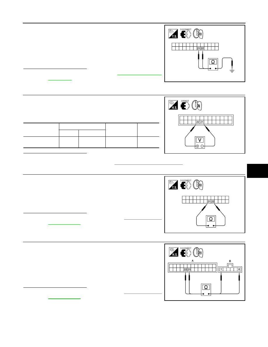
1. Turn ignition switch OFF.
2. Disconnect the A/C auto amp. harness connector.
3. Check continuity between A/C auto amp. harness connector
M49 terminal 21, 22 and ground.
Is the inspection result normal?
OK
>> Replace A/C auto amp. Refer to
NO
>> Repair or replace harness as necessary.
3.
CHECK A/C AUTO AMP. FOR GROUND AND POWER
1. Press the BACK button to back out of self-diagnostic mode.
2. Check voltage between A/C auto amp. harness connector M49
terminal 21 and terminal 22 while placing the HVAC system into
self-diagnostic mode.
Is the inspection result normal?
OK
>> GO TO 4.
NO
>> Replace A/C auto amp. Refer to
VTL-7, "Removal and Installation"
.
4.
CHECK INTAKE DOOR MOTOR AND CIRCUITS FOR OPEN
1. Turn ignition switch OFF.
2. Disconnect the A/C auto amp. harness connector.
3. Check continuity between A/C auto amp. harness connector
M49 terminal 21 and terminal 22.
Is the inspection result normal?
OK
>> Replace intake door motor. Refer to
.
NO
>> GO TO 5.
5.
CHECK INTAKE DOOR MOTOR CIRCUITS FOR OPEN
1. Disconnect the intake door motor harness connector.
2. Check continuity between A/C auto amp. harness connector
M49 (A) terminal 21, 22 and the intake door motor harness con-
nector M58 (B) terminal 1, 6.
Is the inspection result normal?
YES
>> Replace intake door motor. Refer to
.
NO
>> Repair or replace harness as necessary.
21 - Ground
: Continuity should not exist.
22 - Ground
: Continuity should not exist.
AWIIA0147ZZ
Connector
Terminals
Condition
Voltage
(Approx.)
(+) (-)
A/C auto amp.:
M49
22 21
Self-diagnostic
mode
Battery
voltage
AWIIA0148ZZ
Continuity should exist.
AWIIA0149ZZ
21 - 6
: Continuity should exist.
22 - 1
: Continuity should exist.
AWIIA0234ZZ
HAC-42
< COMPONENT DIAGNOSIS >
[AUTOMATIC AIR CONDITIONER]
DEFROSTER DOOR MOTOR CIRCUIT
DEFROSTER DOOR MOTOR CIRCUIT
System Description
INFOID:0000000005147697
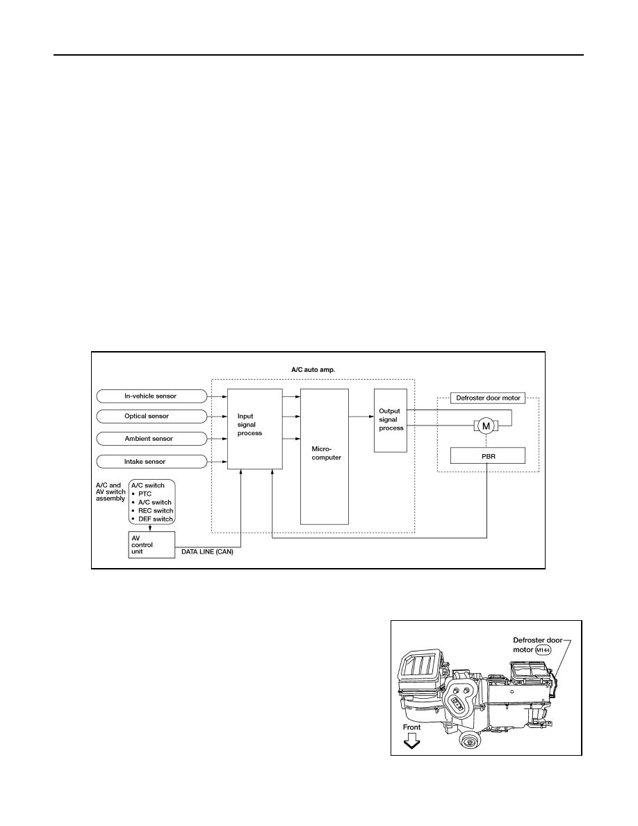
SYSTEM DESCRIPTION
Component Parts
Defroster door control system components are:
• A/C auto amp.
• A/C and AV switch assembly
• Defroster door motor
• PBR (Built into defroster door motor)
• In-vehicle sensor
• Ambient sensor
• Optical sensor
• Intake sensor
System Operation
The A/C auto amp. determines defroster door position based on the position of the defroster switch. When the
defroster switch is depressed, the defroster door motor rotates directing air to the defroster ducts. When any
mode other than defroster is selected, the defroster motor rotates in the opposite direction closing off air flow
to the defroster ducts.
In the AUTO mode, the A/C auto amp. determines defroster door position based on the ambient temperature,
the intake air temperature and the in-vehicle temperature.
COMPONENT DESCRIPTION
Defroster door motor
The defroster door motor is attached to the front heater & cooling
unit assembly. The A/C auto amp. sends a voltage to rotate to the
defroster door directing the air flow either to the defroster ducts, or to
the floor ducts, depending on which way the voltage and ground are
applied to the motor leads. Motor rotation is conveyed to a lever
which activates the defroster door.
AWIIA0151GB
WJIA0592E
DEFROSTER DOOR MOTOR CIRCUIT
HAC-43
< COMPONENT DIAGNOSIS >
[AUTOMATIC AIR CONDITIONER]
C
D
E
F
G
H
J
K
L
M
A
B
HAC
N
O
P
Defroster Door Motor Component Function Check
INFOID:0000000005147698
INSPECTION FLOW
1.
CONFIRM SYMPTOM BY PERFORMING OPERATIONAL CHECK - DEFROSTER DOOR
1. Press the mode switch and select vent (
).
2. Press the defrost switch (
). Defroster indicator should illuminate (on display).
3. Listen for defroster door position change (blower sound should change slightly).
Is the inspection result normal?
YES
>> Inspection End.
NO
>> Go to diagnosis procedure. Refer to
HAC-43, "Defroster Door Motor Diagnosis Procedure"
Defroster Door Motor Diagnosis Procedure
INFOID:0000000005147699
Regarding Wiring Diagram information, refer to
SYMPTOM:
• Defroster door does not change.
• Defroster door motor does not operate normally.
DIAGNOSTIC PROCEDURE FOR DEFROSTER DOOR MOTOR
1.
CHECK A/C AUTO AMP. FOR POWER AND GROUND
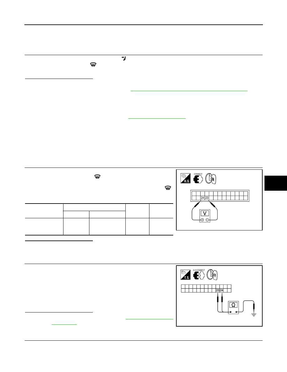
1. Turn ignition switch ON.
2. Press the defroster switch (
).
3. Check voltage between A/C auto amp. harness connector M49
terminal 24 and terminal 23 and press the defroster switch (
)
again.
Is the inspection result normal?
YES
>> GO TO 3.
NO
>> GO TO 2.
2.
CHECK DEFROSTER DOOR MOTOR CIRCUITS FOR SHORT TO GROUND
1. Turn ignition switch OFF.
2. Disconnect the A/C auto amp. harness connector.
3. Check continuity between A/C auto amp. harness connector
M49 terminal 23, 24 and ground.
Is the inspection result normal?
YES
>> Replace A/C auto amp. Refer to
NO
>> Repair or replace harness as necessary.
3.
CHECK A/C AUTO AMP. FOR GROUND AND POWER
Connector
Terminals
Condition
Voltage
(Approx.)
(+) (-)
A/C auto amp.:
M49
24 23
Press de-
froster
switch
Battery
voltage
AWIIA0152ZZ
23 - Ground
: Continuity should not exist.
24 - Ground
: Continuity should not exist.
AWIIA0153ZZ
HAC-44
< COMPONENT DIAGNOSIS >
[AUTOMATIC AIR CONDITIONER]
DEFROSTER DOOR MOTOR CIRCUIT
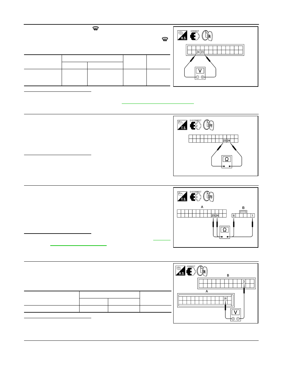
1. Press the defroster switch (
).
2. Check voltage between A/C auto amp. harness connector M49
terminal 23 and terminal 24 and press the defroster switch (
)
again.
Is the inspection result normal?
YES
>> GO TO 4.
NO
>> Replace A/C auto amp. Refer to
VTL-7, "Removal and Installation"
4.
CHECK DEFROSTER DOOR MOTOR AND CIRCUITS FOR OPEN
1. Turn ignition switch OFF.
2. Disconnect the A/C auto amp. harness connector.
3. Check continuity between A/C auto amp. harness connector
M49 terminal 23 and terminal 24.
Is the inspection result normal?
YES
>> GO TO 6.
NO
>> GO TO 5.
5.
CHECK DEFROSTER DOOR MOTOR CIRCUITS FOR OPEN
1. Disconnect the defroster door motor harness connector.
2. Check continuity between A/C auto amp. harness connector
M49 (A) terminal 23, 24 and the defroster door motor harness
connector M144 (B) terminal 1, 6.
Is the inspection result normal?
YES
>> Replace defroster door motor. Refer to
.
NO
>> Repair or replace harness as necessary.
6.
CHECK A/C AUTO AMP. FOR PBR POWER AND GROUND
1. Reconnect A/C auto amp. harness connector.
2. Turn ignition switch ON.
3. Check voltage between A/C auto amp. harness connector M50
(A) terminal 28 and M49 (B) terminal 3.
Is the inspection result normal?
YES
>> GO TO 8.
NO
>> GO TO 7.
7.
CHECK PBR REFERENCE VOLTAGE CIRCUIT FOR SHORT TO GROUND
Connector
Terminals
Condition
Voltage
(Approx.)
(+) (-)
A/C auto amp.:
M49
23 24
Press de-
froster
switch
Battery
voltage
AWIIA0154ZZ
Continuity should exist.
AWIIA0155ZZ
23 - 1
: Continuity should exist.
24 - 6
: Continuity should exist.
AWIIA0156ZZ
Connector
Terminals
Voltage (Ap-
prox.)
(+)
(-)
A/C auto amp.: M50, M49
28
3
5V
AWIIA0118ZZ
Нет комментариевНе стесняйтесь поделиться с нами вашим ценным мнением.
Текст