Infiniti QX56 (JA60). Manual — part 1006
WCS-22
< COMPONENT DIAGNOSIS >
KEY SWITCH SIGNAL CIRCUIT
Is the inspection result normal?
YES
>> GO TO 4
NO
>> Repair harness or connector.
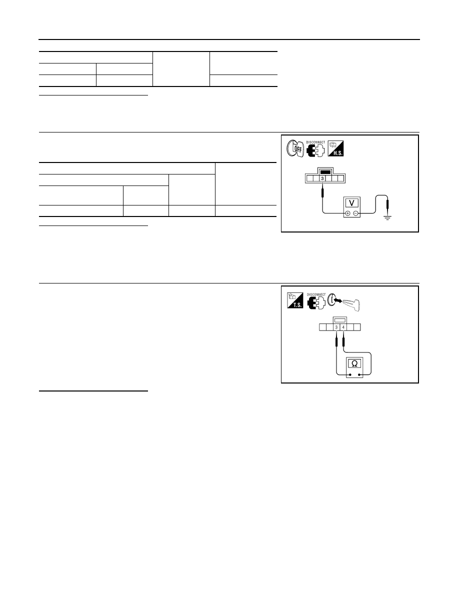
4.
CHECK KEY SWITCH POWER SUPPLY CIRCUIT
Check voltage between key switch and ignition knob switch harness
connector and ground.
Is the inspection result normal?
YES
>> Replace key switch and ignition knob switch.
NO
>> Repair harness or connector.
Component Inspection
INFOID:0000000005146165
1.
CHECK KEY SWITCH
1. Turn ignition switch OFF.
2. Disconnect key switch and ignition knob switch connector.
3. Check continuity between key switch and ignition knob switch
terminals 3 and 4.
Is the inspection result normal?
YES
>> Inspection End.
NO
>> Replace key switch and ignition knob switch.
A
Ground
Continuity
Connector
Terminal
M18
37
No
Terminals
Voltage
(Approx.)
(+)
(
−)
Key switch and ignition
knob switch connector
Terminal
M12
3
Ground
Battery voltage
AWNIA0160ZZ
3 – 4
When key is inserted
into key cylinder
: Continuity should exist.
When key is removed
from key cylinder
: Continuity should not exist.
AWNIA0158ZZ
WCS
WARNING CHIME SYSTEM
WCS-23
< COMPONENT DIAGNOSIS >
C
D
E
F
G
H
I
J
K
L
M
B
A
O
P
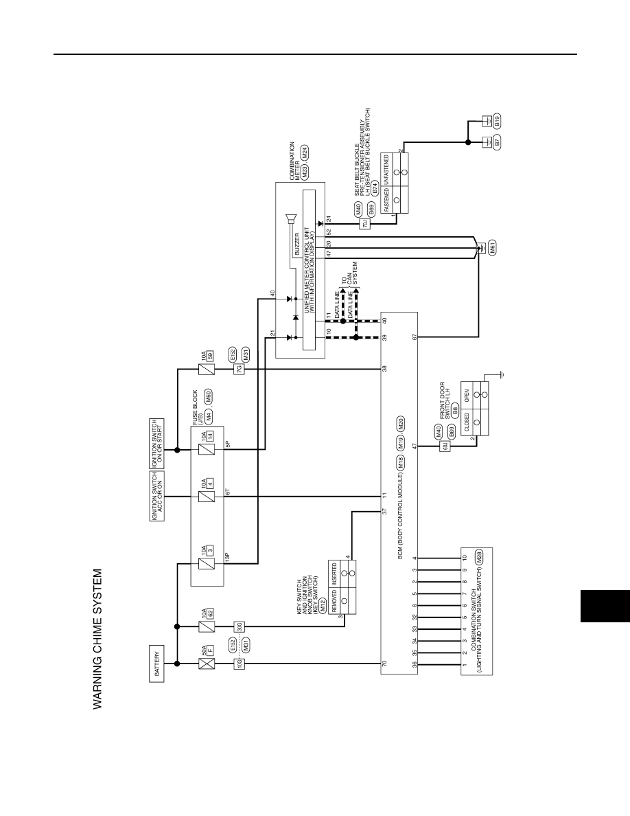
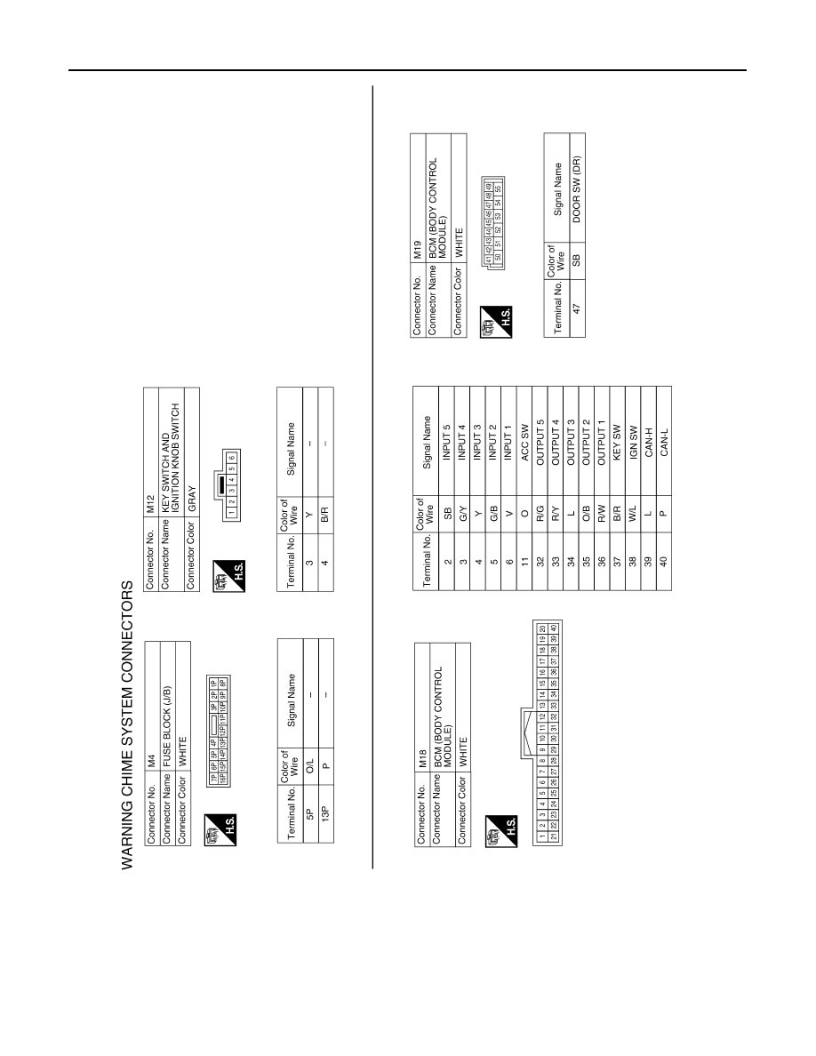
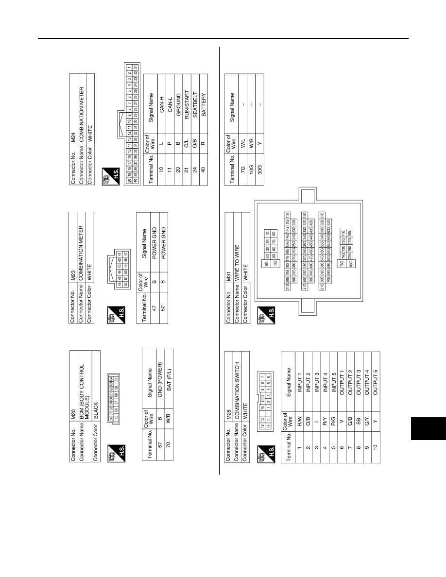
WARNING CHIME SYSTEM
Wiring Diagram
INFOID:0000000005146166
ABNWA0418GB
WCS-24
< COMPONENT DIAGNOSIS >
WARNING CHIME SYSTEM
ABNIA1365GB
WCS
WARNING CHIME SYSTEM
WCS-25
< COMPONENT DIAGNOSIS >
C
D
E
F
G
H
I
J
K
L
M
B
A
O
P
ABNIA1314GB
Нет комментариевНе стесняйтесь поделиться с нами вашим ценным мнением.
Текст