Infiniti QX56 (JA60). Manual — part 398
EC-244
< COMPONENT DIAGNOSIS >
[VK56DE]
P0451 EVAP CONTROL SYSTEM PRESSURE SENSOR
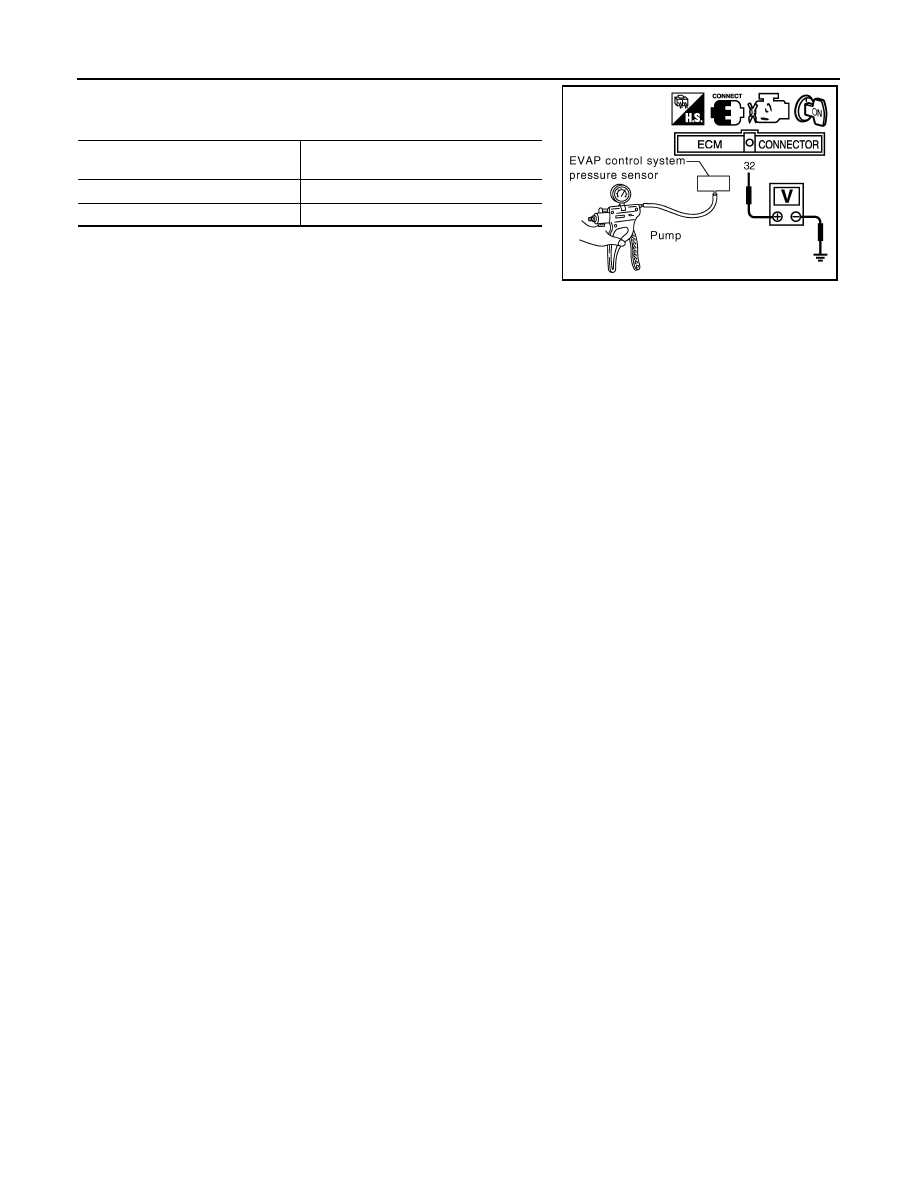
3. Turn ignition switch ON and check output voltage between ECM
terminal 32 and ground under the following conditions.
CAUTION:
• Always calibrate the vacuum pump gauge when using it.
• Do not apply below -93.3 kPa (-700 mmHg, -27.56 inHg) or
pressure over 101.3 kPa (760 mmHg, 29.92 inHg).
4. If NG, replace EVAP control system pressure sensor.
Applied vacuum kPa
(mmHg, inHg)
Voltage (V)
Not applied
1.8 - 4.8
-26.7 (-200, -7.87)
2.1 to 2.5 lower than above value
PBIB1173E
P0452 EVAP CONTROL SYSTEM PRESSURE SENSOR
EC-245
< COMPONENT DIAGNOSIS >
[VK56DE]
C
D
E
F
G
H
I
J
K
L
M
A
EC
N
P
O
P0452 EVAP CONTROL SYSTEM PRESSURE SENSOR
Component Description
INFOID:0000000005149267
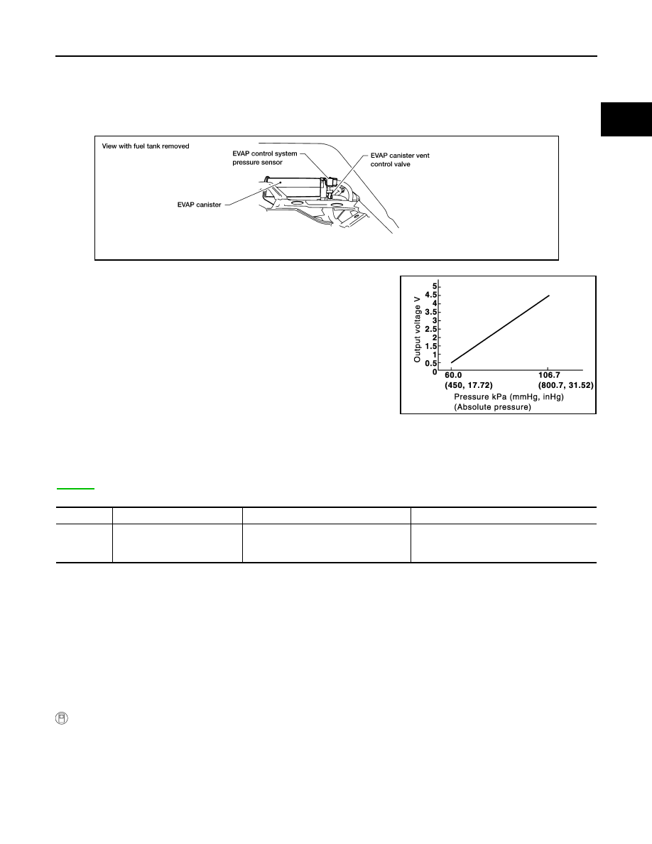
The EVAP control system pressure sensor detects pressure in the purge line. The sensor output voltage to the
ECM increases as pressure increases.
On Board Diagnosis Logic
INFOID:0000000005149268
NOTE:
If DTC P0452 is displayed with DTC P0643, first perform the trouble diagnosis for DTC P0643. Refer to
.
DTC Confirmation Procedure
INFOID:0000000005149269
NOTE:
If DTC Confirmation Procedure has been previously conducted, always perform the following procedure
before conducting the next step.
1. Turn ignition switch OFF and wait at least 10 seconds.
2. Turn ignition switch ON.
3. Turn ignition switch OFF and wait at least 10 seconds.
TESTING CONDITION:
Always perform test at a temperature of 5
°C (41°F) or more.
WITH CONSULT-III
1. Start engine and warm it up to normal operating temperature.
2. Turn ignition switch OFF and wait at least 10 seconds.
3. Turn ignition switch ON.
4. Select “DATA MONITOR” mode with CONSULT-III.
5. Make sure that “FUEL T/TMP SE” is more than 0
°C (32°F).
BBIA0443E
PBIB1207E
DTC No.
Trouble diagnosis name
DTC detecting condition
Possible cause
P0452
0452
EVAP control system pressure
sensor low input
An excessively low voltage from the sen-
sor is sent to ECM.
• Harness or connectors
(The sensor circuit is open or shorted.)
• EVAP control system pressure sensor
EC-246
< COMPONENT DIAGNOSIS >
[VK56DE]
P0452 EVAP CONTROL SYSTEM PRESSURE SENSOR
6. Start engine and wait at least 20 seconds.
7. Check 1st trip DTC.
8. If 1st trip DTC is detected, go to
WITH GST
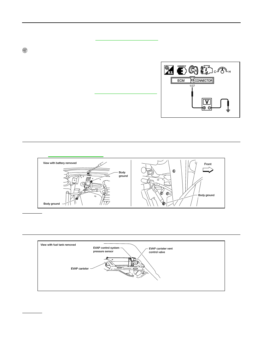
1. Start engine and warm it up to normal operating temperature.
2. Check that voltage between ECM terminal 107 (Fuel tank tem-
perature sensor signal) and ground is less than 4.2 V.
3. Turn ignition switch OFF and wait at least 10 seconds.
4. Start engine and wait at least 20 seconds.
5. Select Service $07 with GST.
If 1st trip DTC is detected, go to
.
Diagnosis Procedure
INFOID:0000000005149270
1.
CHECK GROUND CONNECTIONS
1. Turn ignition switch OFF.
2. Loosen and retighten three ground screws on the body.
OK or NG
OK
>> GO TO 2.
NG
>> Repair or replace ground connections.
2.
CHECK CONNECTOR
1. Disconnect EVAP control system pressure sensor harness connector.
2. Check sensor harness connector for water.
OK or NG
OK
>> GO TO 3.
NG
>> Repair or replace harness connector.
PBIB1110E
BBIA0354E
Water should not exist.
BBIA0443E
P0452 EVAP CONTROL SYSTEM PRESSURE SENSOR
EC-247
< COMPONENT DIAGNOSIS >
[VK56DE]
C
D
E
F
G
H
I
J
K
L
M
A
EC
N
P
O
3.
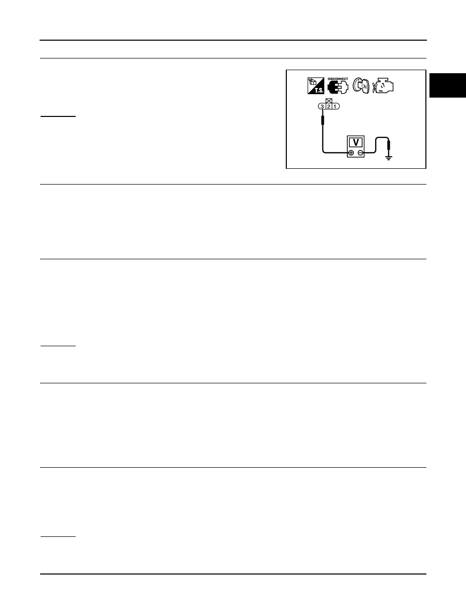
CHECK EVAP CONTROL SYSTEM PRESSURE SENSOR POWER SUPPLY CIRCUIT
1. Turn ignition switch ON.
2. Check voltage between EVAP control system pressure sensor
terminal 3 and ground with CONSULT-III or tester.
OK or NG
OK
>> GO TO 5.
NG
>> GO TO 4.
4.
DETECT MALFUNCTIONING PART
Check the following.
• Harness connectors C1, E41
• Harness connectors E5, F14
• Harness for open or short between EVAP control system pressure sensor and ECM
>> Repair open circuit or short to ground or short to power in harness or connectors.
5.
CHECK EVAP CONTROL SYSTEM PRESSURE SENSOR GROUND CIRCUIT FOR OPEN AND SHORT
1. Turn ignition switch OFF.
2. Disconnect ECM harness connector.
3. Check harness continuity between EVAP control system pressure sensor terminal 1 and ECM terminal
67.
Refer to Wiring Diagram.
4. Also check harness for short to ground and short to power.
OK or NG
OK
>> GO TO 7.
NG
>> GO TO 6.
6.
DETECT MALFUNCTIONING PART
Check the following.
• Harness connectors C1, E41
• Harness connectors E5, F14
• Harness for open or short between EVAP control system pressure sensor and ECM
>> Repair open circuit or short to ground or short to power in harness or connectors.
7.
CHECK EVAP CONTROL SYSTEM PRESSURE SENSOR INPUT SIGNAL CIRCUIT FOR OPEN AND
SHORT
1. Check harness continuity between ECM terminal 32 and EVAP control system pressure sensor terminal
2.
Refer to Wiring Diagram.
2. Also check harness for short to ground and short to power.
OK or NG
OK
>> GO TO 9.
NG
>> GO TO 8.
8.
DETECT MALFUNCTIONING PART
Voltage: Approximately 5V
PBIB0138E
Continuity should exist.
Continuity should exist.
Нет комментариевНе стесняйтесь поделиться с нами вашим ценным мнением.
Текст