Infiniti QX56 (JA60). Manual — part 699
MWI
POWER SUPPLY AND GROUND CIRCUIT
MWI-31
< COMPONENT DIAGNOSIS >
C
D
E
F
G
H
I
J
K
L
M
B
A
O
P
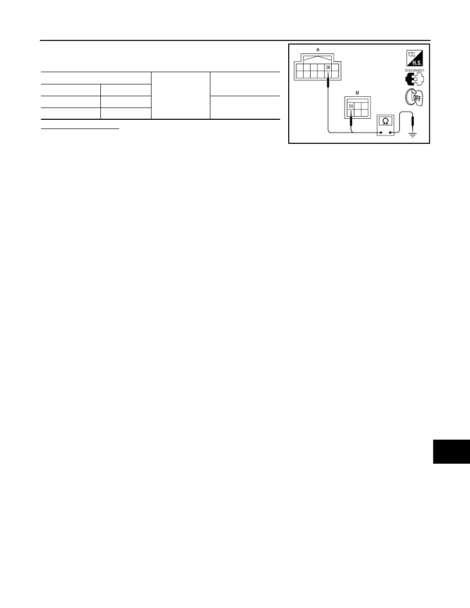
2. Check continuity between IPDM E/R harness connectors and
ground.
Does continuity exist?
YES
>> Inspection End.
NO
>> Repair or replace harness.
IPDM E/R
Ground
Continuity
Connector
Terminal
E122 (A)
38
Yes
E124 (B)
59
AWMIA0024ZZ
MWI-32
< COMPONENT DIAGNOSIS >
FUEL LEVEL SENSOR SIGNAL CIRCUIT
FUEL LEVEL SENSOR SIGNAL CIRCUIT
Description
INFOID:0000000005146081
The fuel level sensor unit and fuel pump detects the approximate fuel level in the fuel tank and transmits the
fuel level signal to the combination meter.
Component Function Check
INFOID:0000000005146082
1.
COMBINATION METER INPUT SIGNAL
1. Select “METER/M&A” on CONSULT-III.
2. Using “FUEL METER” of “DATA MONITOR”, compare the value of DATA MONITOR with fuel gauge
pointer of combination meter.
Does the data monitor value approximately match the fuel gauge indication?
YES
>> Inspection End.
NO
>> Replace combination meter. Refer to
MWI-100, "Removal and Installation"
Diagnosis Procedure
INFOID:0000000005146083
Regarding Wiring Diagram information, refer to
.
1.
CHECK HARNESS CONNECTOR
1. Turn ignition switch OFF.
2. Check combination meter and fuel level sensor unit terminals (meter-side and harness-side) for poor con-
nection.
Is the inspection result normal?
YES
>> GO TO 2
NO
>> Repair or replace terminals or connectors.
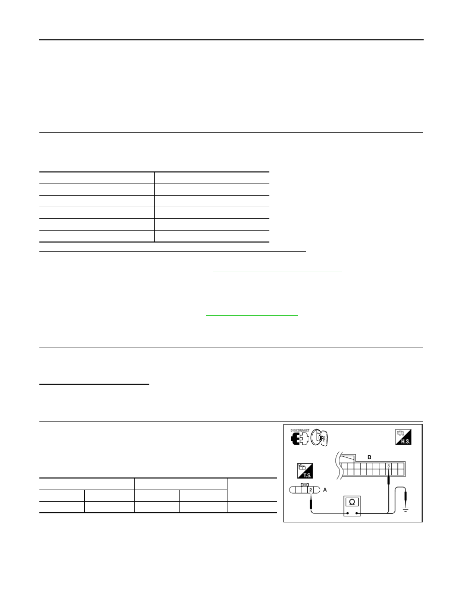
2.
CHECK FUEL LEVEL SENSOR UNIT CIRCUIT
1. Disconnect combination meter connector and fuel level sensor
unit connector.
2. Check continuity between combination meter harness connector
(B) and fuel level sensor unit and fuel pump harness connector
(A).
3. Check continuity between fuel level sensor unit and fuel pump
harness connector (A) and ground.
Fuel gauge pointer
Reference value of data monitor [lit.]
Full
Approx. 93
3/4
Approx. 73
1/2
Approx. 52
1/4
Approx. 30
Empty
Approx. 11
A
B
Continuity
Connector
Terminal
Connector
Terminal
C5
2
M24
3
Yes
AWNIA0206ZZ

MWI
FUEL LEVEL SENSOR SIGNAL CIRCUIT
MWI-33
< COMPONENT DIAGNOSIS >
C
D
E
F
G
H
I
J
K
L
M
B
A
O
P
Is the inspection result normal?
YES
>> GO TO 3
NO
>> Repair harness or connector.
3.
CHECK FUEL LEVEL SENSOR UNIT GROUND CIRCUIT
1. Check continuity between combination meter harness connector
(B) and fuel level sensor unit and fuel pump harness connector
(A).
2. Check continuity between fuel level sensor unit and fuel pump
harness connector (A) and ground.
Is the inspection result normal?
YES
>> GO TO 4
NO
>> Repair harness or connector.
4.
CHECK INSTALLATION CONDITION
Check fuel level sensor unit installation, and check whether the float arm interferes or binds with any of the
internal components in the fuel tank.
Is the inspection result normal?
YES
>> Inspection End.
NO
>> Install the fuel level sensor unit properly.
Component Inspection
INFOID:0000000005146084
1.
REMOVE FUEL LEVEL SENSOR UNIT
Remove the fuel level sensor unit. Refer to
FL-7, "Removal and Installation"
.
>> GO TO 2
2.
CHECK FUEL LEVEL SENSOR UNIT AND FUEL PUMP
Check the resistance between terminals 2 and 5.
*1 and *2: When float arm is in contact with stopper.
Is inspection result normal?
YES
>> Inspection End.
NO
>> Replace fuel level sensor unit and fuel pump. Refer to
FL-7, "Removal and Installation"
.
A
Ground
Continuity
Connector
Terminal
C5
2
No
A
B
Continuity
Connector
Terminal
Connector
Terminal
C5
5
M24
4
Yes
A
Ground
Continuity
Connector
Terminal
C5
5
No
AWNIA0207ZZ
Terminal
Float position
mm (in)
Resistance value
(Approx.)
2
5
*1
Empty
7.5 (0.3)
80
Ω
*2
Full
218.9 (8.6)
6
Ω
LKIA0402E
MWI-34
< COMPONENT DIAGNOSIS >
OIL PRESSURE SWITCH SIGNAL CIRCUIT
OIL PRESSURE SWITCH SIGNAL CIRCUIT
Description
INFOID:0000000005146085
Detects the engine oil pressure and transmits the oil pressure switch signal to the IPDM E/R.
Component Function Check
INFOID:0000000005146086
1.
COMBINATION METER INPUT SIGNAL
1. Select “METER/M&A” on CONSULT-III.
2. Monitor “OIL W/L” of “DATA MONITOR” while operating ignition switch.
>> Inspection End.
Diagnosis Procedure
INFOID:0000000005146087
Regarding Wiring Diagram information, refer to
.
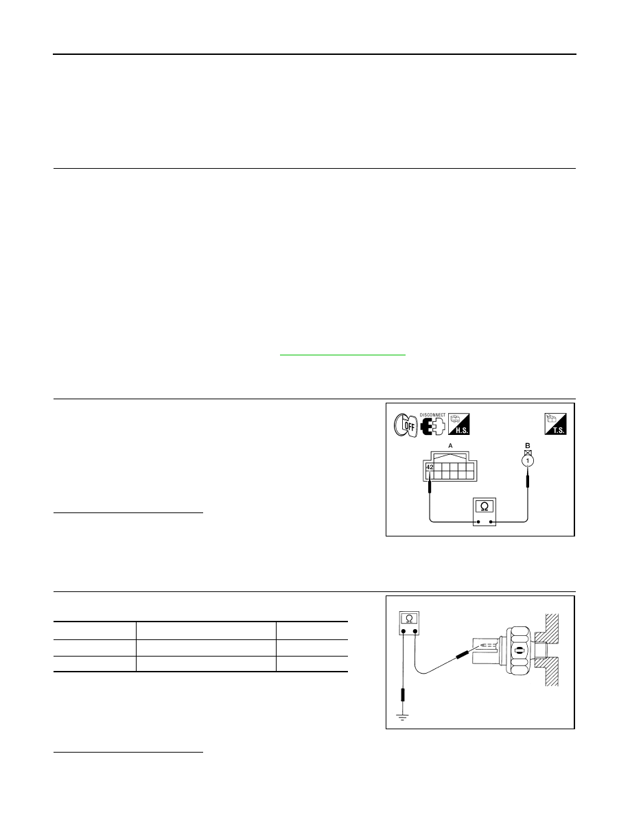
1.
CHECK OIL PRESSURE SWITCH CIRCUIT
1. Turn ignition switch OFF.
2. Disconnect IPDM E/R connector E122 and oil pressure switch
connector F4.
3. Check continuity between IPDM E/R harness connector E122
(A) terminal 42 and oil pressure switch harness connector F4 (B)
terminal 1.
Is the inspection result normal?
YES
>> Inspection End.
NO
>> Repair harness or connector.
Component Inspection
INFOID:0000000005146088
1.
CHECK OIL PRESSURE SWITCH
Check continuity between oil pressure switch and ground.
Is the inspection result normal?
YES
>> Inspection End.
NO
>> Replace the oil pressure switch.
OIL W/L
When ignition switch is in ON
position (Engine stopped)
: ON
When engine is running
: OFF
Continuity should exist.
WKIA5607E
Condition
Oil pressure [kPa (kg/cm
2
, psi)]
Continuity
Engine stopped
Less than 29 (0.3, 4)
Yes
Engine running
More than 29 (0.3, 4)
No
ELF0044D
Нет комментариевНе стесняйтесь поделиться с нами вашим ценным мнением.
Текст