Infiniti QX56 (JA60). Manual — part 377
EC-160
< COMPONENT DIAGNOSIS >
[VK56DE]
P0138, P0158 HO2S2
P0138, P0158 HO2S2
Component Description
INFOID:0000000005149178
The heated oxygen sensor 2, after three way catalyst (manifold),
monitors the oxygen level in the exhaust gas on each bank.
Even if switching characteristics of the air fuel ratio (A/F) sensor 1
are shifted, the air-fuel ratio is controlled to stoichiometric, by the sig-
nal from the heated oxygen sensor 2.
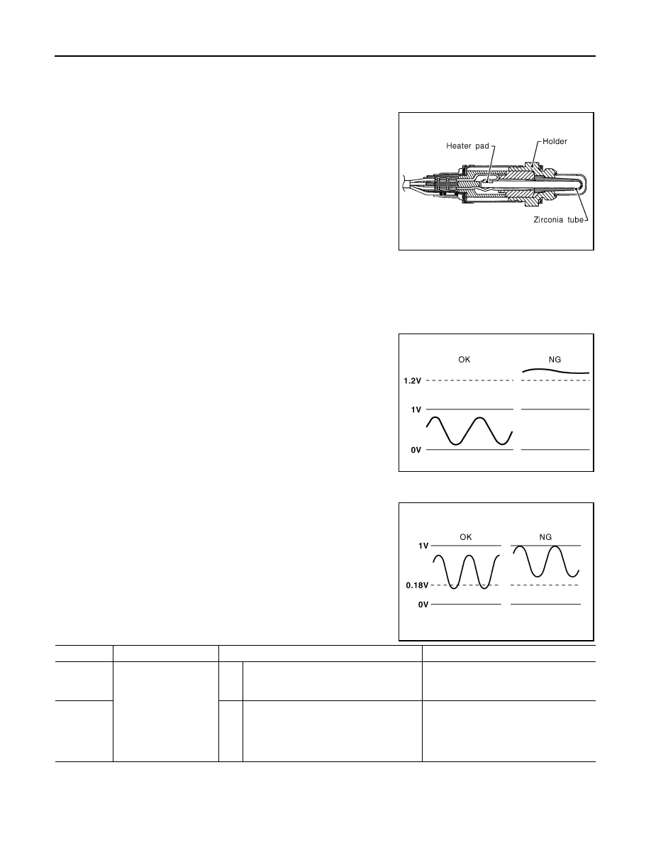
This sensor is made of ceramic zirconia. The zirconia generates volt-
age from approximately 1V in richer conditions to 0V in leaner condi-
tions.
Under normal conditions the heated oxygen sensor 2 is not used for
engine control operation.
On Board Diagnosis Logic
INFOID:0000000005149179
The heated oxygen sensor 2 has a much longer switching time between rich and lean than the air fuel ratio (A/
F) sensor 1. The oxygen storage capacity of the three way catalyst (manifold) causes the longer switching
time.
MALFUNCTION A
To judge the malfunctions of heated oxygen sensor 2, ECM monitors
whether the voltage is unusually high during the various driving con-
dition such as fuel-cut.
MALFUNCTION B
To judge the malfunctions of heated oxygen sensor 2, ECM monitors
whether the minimum voltage of sensor is sufficiently low during the
various driving condition such as fuel-cut.
DTC Confirmation Procedure
INFOID:0000000005149180
Perform PROCEDURE FOR MALFUNCTION A first.
SEF327R
PBIB1848E
PBIB2376E
DTC No.
Trouble diagnosis name
DTC detecting condition
Possible cause
P0138
0138
(Bank 1)
Heated oxygen sensor 2
circuit high voltage
A)
An excessively high voltage from the sen-
sor is sent to ECM.
• Harness or connectors
(The sensor circuit is open or shorted)
• Heated oxygen sensor 2
P0158
0158
(Bank 2)
B)
The minimum voltage from the sensor is
not reached to the specified voltage.
• Harness or connectors
(The sensor circuit is open or shorted)
• Heated oxygen sensor 2
• Fuel pressure
• Fuel injector

P0138, P0158 HO2S2
EC-161
< COMPONENT DIAGNOSIS >
[VK56DE]
C
D
E
F
G
H
I
J
K
L
M
A
EC
N
P
O
If DTC cannot be confirmed, perform PROCEDURE FOR MALFUNCTION B.
NOTE:
If DTC Confirmation Procedure has been previously conducted, always perform the following procedure
before conducting the next step.
1. Turn ignition switch OFF and wait at least 10 seconds.
2. Turn ignition switch ON.
3. Turn ignition switch OFF and wait at least 10 seconds.
PROCEDURE FOR MALFUNCTION A
With CONSULT-III
1. Turn ignition switch ON and select “DATA MONITOR” mode with CONSULT-III.
2. Start engine and warm it up to the normal operating temperature.
3. Turn ignition switch OFF and wait at least 10 seconds.
4. Turn ignition switch ON.
5. Turn ignition switch OFF and wait at least 10 seconds.
6. Start engine and keep the engine speed between 3,500 and 4,000 rpm for at least 1 minute under no load.
7. Let engine idle for 2 minutes.
8. Check 1st trip DTC.
9. If 1st trip DTC is detected, go to
With GST
Follow the procedure “With CONSULT-III” above.
PROCEDURE FOR MALFUNCTION B
With CONSULT-III
TESTING CONDITION:
For better results, perform “DTC WORK SUPPORT” at a temperature of 0 to 30
°C (32 to 86 °F).
1. Turn ignition switch ON and select “DATA MONITOR” mode with CONSULT-III.
2. Start engine and warm it up to the normal operating temperature.
3. Turn ignition switch OFF and wait at least 10 seconds.
4. Start engine and keep the engine speed between 3,500 and 4,000 rpm for at least 1 minute under no load.
5. Let engine idle for 1 minute.
6. Make sure that “COOLAN TEMP/S” indicates more than 70
°C (158°F).
If not, warm up engine and go to next step when “COOLAN TEMP/S” indication reaches to 70
°C (158°F).
7. Open engine hood.
8. Select “HO2S2 (B1) P1146” (for DTC P0138) or “HO2S2 (B2) P1166” (for DTC P0158) of “HO2S2” in
“DTC WORK SUPPORT” mode with CONSULT-III.
9. Following the instruction of CONSULT-III.
NOTE:
It will take at most 10 minutes until “COMPLETED” is displayed.
10. Make sure that “OK” is displayed after touching “SELF-DIAG RESULTS”.
If “NG” is displayed, refer to
.
If “CAN NOT BE DIAGNOSED” is displayed, perform the following.
a. Turn ignition switch OFF and leave the vehicle in a cool place (soak the vehicle).
b. Return to step 1.
Overall Function Check
INFOID:0000000005149181
PROCEDURE FOR MALFUNCTION B
Use this procedure to check the overall function of the heated oxygen sensor 2 circuit. During this check, a 1st
trip DTC might not be confirmed.
With GST
1. Start engine and warm it up to the normal operating temperature.
EC-162
< COMPONENT DIAGNOSIS >
[VK56DE]
P0138, P0158 HO2S2
2. Turn ignition switch OFF and wait at least 10 seconds.
3. Start engine and keep the engine speed between 3,500 and 4,000 rpm for at least 1 minute under no load.
4. Let engine idle for 1 minute.
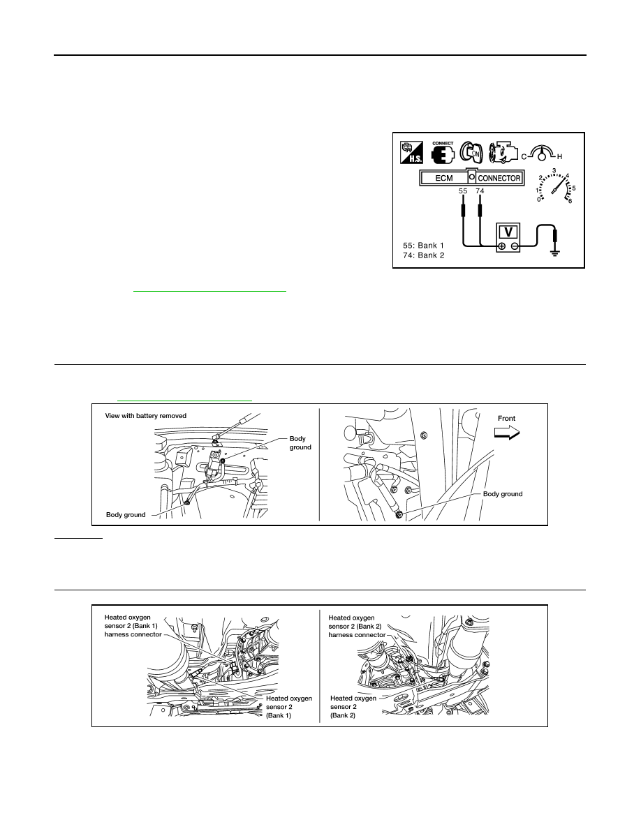
5. Set voltmeter probes between ECM terminal 55 [HO2S2 (B2) signal] or 74 [HO2S2 (B1) signal] and
ground.
6. Check the voltage when revving up to 4,000 rpm under no load
at least 10 times.
(Depress and release accelerator pedal as soon as possible.)
The voltage should be below 0.18 V at least once during this
procedure.
If the voltage can be confirmed in step 6, step 7 is not nec-
essary.
7. Keep vehicle at idling for 10 minutes, then check the voltage. Or
check the voltage when coasting from 80 km/h (50 MPH) in D
position.
The voltage should be below 0.18 V at least once during this
procedure.
8. If NG, go to
Diagnosis Procedure
INFOID:0000000005149182
PROCEDURE FOR MALFUNCTION A
1.
CHECK GROUND CONNECTIONS
1. Turn ignition switch OFF.
2. Loosen and retighten two ground screws on the body.
OK or NG
OK
>> GO TO 2.
NG
>> Repair or replace ground connections.
2.
CHECK HO2S2 GROUND CIRCUIT FOR OPEN AND SHORT
1. Disconnect heated oxygen sensor 2 harness connector.
2. Disconnect ECM harness connector.
3. Check harness continuity between ECM terminal 78 and HO2S2 terminal 4.
Refer to Wiring Diagram.
PBIB2054E
BBIA0354E
Continuity should exist.
BBIA0435E

P0138, P0158 HO2S2
EC-163
< COMPONENT DIAGNOSIS >
[VK56DE]
C
D
E
F
G
H
I
J
K
L
M
A
EC
N
P
O
4. Also check harness for short to ground and short to power.
OK or NG
OK
>> GO TO 3.
NG
>> Repair open circuit or short to ground or short to power in harness or connectors.
3.
CHECK HO2S2 INPUT SIGNAL CIRCUIT FOR OPEN AND SHORT
1. Check harness continuity between ECM terminal and HO2S2 terminal as follows.
Refer to Wiring Diagram.
2. Check harness continuity between the following terminals and ground.
Refer to Wiring Diagram.
3. Also check harness for short to power.
OK or NG
OK
>> GO TO 4.
NG
>> Repair open circuit or short to ground or short to power in harness or connectors.
4.
CHECK HO2S2 CONNECTOR FOR WATER
Check connectors for water.
OK or NG
OK
>> GO TO 5.
NG
>> Repair or replace harness or connectors.
5.
CHECK HEATED OXYGEN SENSOR 2
EC-165, "Component Inspection"
OK or NG
OK
>> GO TO 6.
NG
>> Replace malfunctioning heated oxygen sensor 2.
6.
CHECK INTERMITTENT INCIDENT
GI-35, "How to Check Terminal"
GI-38, "Intermittent Incident"
>> INSPECTION END
PROCEDURE FOR MALFUNCTION B
1.
CHECK GROUND CONNECTIONS
1. Turn ignition switch OFF.
2. Loosen and retighten two ground screws on the body.
DTC
Terminals
Bank
ECM
Sensor
P0138
55
1
1
P0158
74
1
2
Continuity should exist.
DTC
Terminals
Bank
ECM
Sensor
P0138
55
1
1
P0158
74
1
2
Continuity should not exist.
Water should not exist.
Нет комментариевНе стесняйтесь поделиться с нами вашим ценным мнением.
Текст