Infiniti QX56 (JA60). Manual — part 944

TM-78
< COMPONENT DIAGNOSIS >
P1730 INTERLOCK
P1730 INTERLOCK
Description
INFOID:0000000005148630
Fail-safe function to detect interlock conditions.
On Board Diagnosis Logic
INFOID:0000000005148631
• This is an OBD-II self-diagnostic item.
• Diagnostic trouble code “P1730 INTERLOCK” with CONSULT-III is detected when TCM does not receive the
proper voltage signal from the sensor and switch.
• TCM monitors and compares gear position and conditions of each ATF pressure switch when gear is steady.
Possible Cause
INFOID:0000000005148632
• Harness or connectors
(The solenoid and switch circuit is open or shorted.)
• Low coast brake solenoid valve
• ATF pressure switch 2
DTC Confirmation Procedure
INFOID:0000000005148633
NOTE:
If “DTC Confirmation Procedure” has been previously performed, always turn ignition switch “OFF”
and wait at least 10 seconds before performing the next test.
After the repair, perform the following procedure to confirm the malfunction is eliminated.
WITH CONSULT-III
1. Turn ignition switch “ON”. (Do not start engine.)
2. Select “DATA MONITOR” mode for “TRANSMISSION” with CONSULT-III.
3. Start engine.
4. Drive vehicle and maintain the following conditions for at least 2 consecutive seconds.
SLCT LVR POSI: “D” position
5. If DTC is detected, go to
WITH GST
Follow the procedure “With CONSULT-III”.
Judgment of Interlock
INFOID:0000000005148634
• When interlock is judged to be malfunctioning, the vehicle should be fixed in 2GR, and should be set in a
condition in which it can travel.
NOTE:
When the vehicle is driven fixed in 2GR, a input speed sensor malfunction is displayed, but this is not a input
speed sensor malfunction.
• When interlock is detected at the 3GR or more, it is locked at the 2GR.
Diagnosis Procedure
INFOID:0000000005148635
1.
SELF-DIAGNOSIS
With CONSULT-III
1. Drive vehicle.
2. Stop vehicle and turn ignition switch “OFF”.
3. Turn ignition switch “ON”.
4. Select “SELF-DIAG RESULTS” mode for “TRANSMISSION” with CONSULT-III.
OK or NG
OK
>> GO TO 2.
NG
>> Check low coast brake solenoid valve circuit and function. Refer to
2.
CHECK DTC
Perform “DTC Confirmation Procedure”.

P1730 INTERLOCK
TM-79
< COMPONENT DIAGNOSIS >
C
E
F
G
H
I
J
K
L
M
A
B
TM
N
O
P
• Refer to
TM-78, "DTC Confirmation Procedure"
OK or NG
OK
>> INSPECTION END
NG
>> GO TO 3.
3.
CHECK TCM POWER SUPPLY AND GROUND CIRCUIT
Check TCM power supply and ground circuit. Refer to
OK or NG
OK
>> GO TO 4.
NG
>> Repair or replace damaged parts.
4.
DETECT MALFUNCTIONING ITEM
Check the following items:
• The A/T assembly harness connector pin terminals for damage or loose connection with harness connector.
OK or NG
OK
>> Replace the control valve with TCM. Refer to
TM-172, "Control Valve with TCM and A/T Fluid
Temperature Sensor 2 and Plug"
.
NG
>> Repair or replace damaged parts.
TM-80
< COMPONENT DIAGNOSIS >
P1731 1ST ENGINE BRAKING
P1731 1ST ENGINE BRAKING
Description
INFOID:0000000005148636
Fail-safe function to prevent sudden decrease in speed by engine brake other than at "1" position.
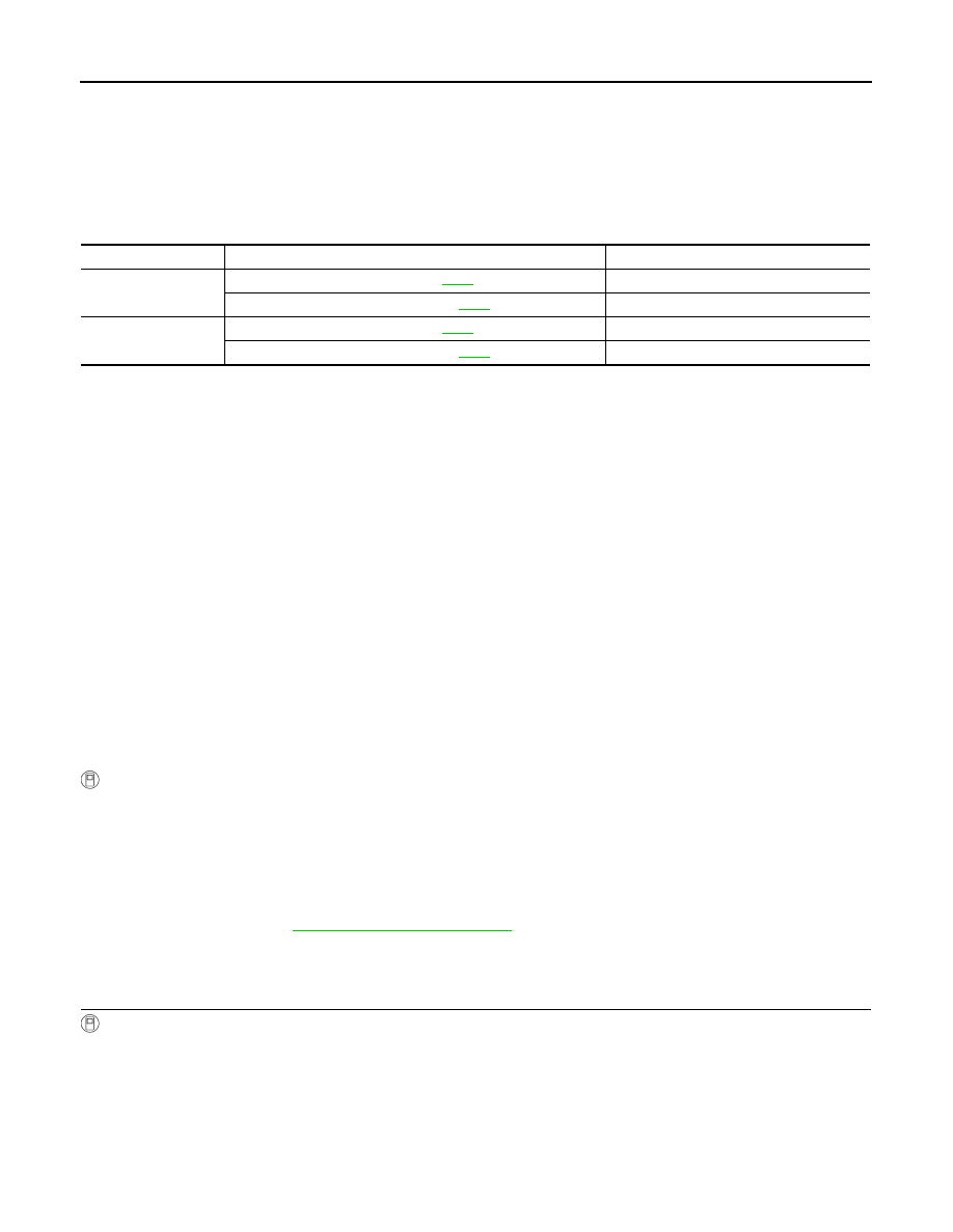
CONSULT-III Reference Value in Data Monitor Mode
INFOID:0000000005148637
On Board Diagnosis Logic
INFOID:0000000005148638
• This is not an OBD-II self-diagnostic item.
• Diagnostic trouble code “P1731 1GR E/BRAKING” with CONSULT-III is detected under the following condi-
tions.
- When TCM does not receive the proper voltage signal from the sensor.
- When TCM monitors ATF pressure switch 2 and solenoid monitor value, and detects as irregular when
engine brake of 1GR acts other than at 1 position.
Possible Cause
INFOID:0000000005148639
• Harness or connectors
(The sensor circuit is open or shorted.)
• Low coast brake solenoid valve
• ATF pressure switch 2
DTC Confirmation Procedure
INFOID:0000000005148640
NOTE:
If “DTC Confirmation Procedure” has been previously preformed, always turn ignition switch “OFF”
and wait at least 10 seconds before performing the next test.
After the repair, perform the following procedure to confirm the malfunction is eliminated.
WITH CONSULT-III
1. Turn ignition switch “ON”. (Do not start engine.)
2. Select “DATA MONITOR” mode for “TRANSMISSION” with CONSULT-III.
3. Start engine.
4. Drive vehicle and maintain the following conditions for at least 2 consecutive seconds.
ENGINE SPEED: 1,200 rpm
SLCT LVR POSI: “1” position
GEAR: 1st
5. If DTC is detected, go to
Diagnosis Procedure
INFOID:0000000005148641
1.
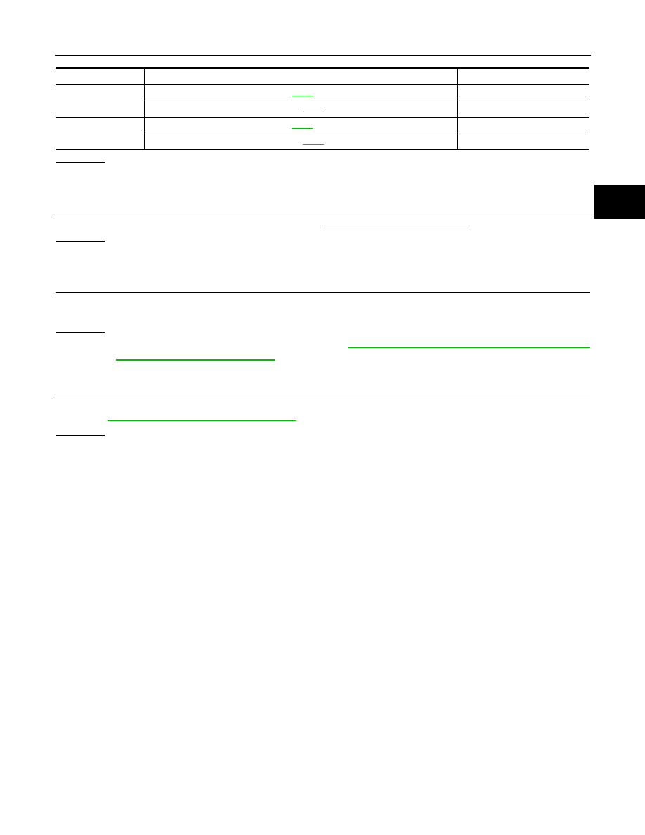
CHECK INPUT SIGNALS
With CONSULT-III
1. Start the engine.
2. Select “SELECTION FROM MENU” in “DATA MONITOR” for "TRANSMISSION" with CONSULT-III"
3. Drive vehicle in the “1” position (1GR), and confirm the ON/OFF actuation of “ATF PRES SW 2” and "ON
OFF SOL".
Item name
Condition
Display value
ON OFF SOL
Low coast brake engaged. Refer to
ON
Low coast brake disengaged. Refer to
.
OFF
ATF PRES SW 2
Low coast brake engaged. Refer to
ON
Low coast brake disengaged. Refer to
.
OFF
P1731 1ST ENGINE BRAKING
TM-81
< COMPONENT DIAGNOSIS >
C
E
F
G
H
I
J
K
L
M
A
B
TM
N
O
P
OK or NG
OK
>> GO TO 4.
NG
>> GO TO 2.
2.
CHECK TCM POWER SUPPLY AND GROUND CIRCUIT
Check TCM power supply and ground circuit. Refer to
OK or NG
OK
>> GO TO 3.
NG
>> Repair or replace damaged parts.
3.
DETECT MALFUNCTIONING ITEM
Check the following items:
• The A/T assembly harness connector pin terminals for damage or loose connection with harness connector.
OK or NG
OK
>> Replace the control valve with TCM. Refer to
TM-172, "Control Valve with TCM and A/T Fluid
Temperature Sensor 2 and Plug"
.
NG
>> Repair or replace damaged parts.
4.
CHECK DTC
Perform “DTC Confirmation Procedure”.
• Refer to
TM-80, "DTC Confirmation Procedure"
OK or NG
OK
>> INSPECTION END
NG
>> GO TO 2.
Item name
Condition
Display value
ON OFF SOL
Low coast brake engaged. Refer to
ON
Low coast brake disengaged. Refer to
.
OFF
ATF PRES SW 2
Low coast brake engaged. Refer to
ON
Low coast brake disengaged. Refer to
.
OFF
Нет комментариевНе стесняйтесь поделиться с нами вашим ценным мнением.
Текст