Infiniti QX56 (JA60). Manual — part 393

EC-224
< COMPONENT DIAGNOSIS >
[VK56DE]
P0442 EVAP CONTROL SYSTEM
NG
>> Replace fuel level sensor unit.
24.
CHECK INTERMITTENT INCIDENT
GI-35, "How to Check Terminal"
and
GI-38, "Intermittent Incident"
>> INSPECTION END
Component Inspection
INFOID:0000000005149241
FUEL TANK VACUUM RELIEF VALVE (BUILT INTO FUEL FILLER CAP)
1. Wipe clean valve housing.
2. Check valve opening pressure and vacuum.
3. If out of specification, replace fuel filler cap as an assembly.
CAUTION:
Use only a genuine fuel filler cap as a replacement. If an incor-
rect fuel filler cap is used, the MIL may come on.
SEF445Y
Pressure: 15.3 - 20.0 kPa (0.156 - 0.204 kg/cm
2
, 2.22 -
2.90 psi)
Vacuum:
−6.0 to −3.3 kPa (−0.061 to −0.034 kg/cm
2
,
−0.87 to −0.48 psi)
SEF943S

P0443 EVAP CANISTER PURGE VOLUME CONTROL SOLENOID VALVE
EC-225
< COMPONENT DIAGNOSIS >
[VK56DE]
C
D
E
F
G
H
I
J
K
L
M
A
EC
N
P
O
P0443 EVAP CANISTER PURGE VOLUME CONTROL SOLENOID VALVE
Description
INFOID:0000000005149242
SYSTEM DESCRIPTION
*1: ECM determines the start signal status by the signals of engine speed and battery voltage.
*2: This signal is sent to the ECM through CAN communication line.
This system controls flow rate of fuel vapor from the EVAP canister. The opening of the vapor by-pass pas-
sage in the EVAP canister purge volume control solenoid valve changes to control the flow rate. The EVAP
canister purge volume control solenoid valve repeats ON/OFF operation according to the signal sent from the
ECM. The opening of the valve varies for optimum engine control. The optimum value stored in the ECM is
determined by considering various engine conditions. When the engine is operating, the flow rate of fuel vapor
from the EVAP canister is regulated as the air flow changes.
COMPONENT DESCRIPTION
The EVAP canister purge volume control solenoid valve uses a ON/
OFF duty to control the flow rate of fuel vapor from the EVAP canis-
ter. The EVAP canister purge volume control solenoid valve is
moved by ON/OFF pulses from the ECM. The longer the ON pulse,
the greater the amount of fuel vapor that will flow through the valve.
On Board Diagnosis Logic
INFOID:0000000005167699
Sensor
Input signal to ECM
ECM function
Actuator
Crankshaft position sensor (POS)
Camshaft position sensor (PHASE)
Engine speed*
1
EVAP canister
purge flow control
EVAP canister purge vol-
ume control solenoid valve
Mass air flow sensor
Amount of intake air
Engine coolant temperature sensor
Engine coolant temperature
Battery
Battery voltage*
1
Throttle position sensor
Throttle position
Accelerator pedal position sensor
Accelerator pedal position
Air fuel ratio (A/F) sensor 1
Density of oxygen in exhaust gas
(Mixture ratio feedback signal)
Fuel tank temperature sensor
Fuel temperature in fuel tank
Wheel sensor
Vehicle speed*
2
PBIB2057E
DTC No.
Trouble diagnosis
name
DTC detecting condition
Possible cause
P0443
0443
EVAP canister purge
volume control sole-
noid valve
A)
The canister purge flow is detected during the
vehicle is stopped while the the engine is run-
ning, even when EVAP canister purge volume
control solenoid valve is completely closed.
• EVAP control system pressure sensor
• EVAP canister purge volume control so-
lenoid valve
(The valve is stuck open.)
• EVAP canister vent control valve
• EVAP canister
• Hoses
(Hoses are connected incorrectly or
clogged.)
B)
The canister purge flow is detected during the
specified driving conditions, even when EVAP
canister purge volume control solenoid valve
is completely closed.
EC-226
< COMPONENT DIAGNOSIS >
[VK56DE]
P0443 EVAP CANISTER PURGE VOLUME CONTROL SOLENOID VALVE
DTC Confirmation Procedure
INFOID:0000000005167700
Perform PROCEDURE FOR MALFUNCTION A first.
If the DTC cannot be confirmed, perform PROCEDURE FOR MALFUNCTION B.
NOTE:
If DTC Confirmation Procedure has been previously conducted, always perform the following procedure
before conducting the next step.
1. Turn ignition switch OFF and wait at least 10 seconds.
2. Turn ignition switch ON.
3. Turn ignition switch OFF and wait at least 10 seconds.
PROCEDURE FOR MALFUNCTION A
TESTING CONDITION:
• Perform “DTC CONFIRMATION PROCEDURE” when the fuel level is between 1/4 and 3/4 full, and
vehicle is placed on flat level surface.
• Always perform test at a temperature of 5 to 60
°C (41°F).
• Cool the vehicle so that engine coolant temperature becomes same level as ambient temperature.
With CONSULT-III
1. Turn ignition switch ON and select “DATA MONITOR” mode with CONSULT-III.
2. Check that the following condition are met.
FUEL T/TMP SE: 0 – 35
°C (32 – 95°F)
3. Start engine and wait at least 60 seconds.
4. Check 1st trip DTC.
5. If 1st trip DTC is detected, go to
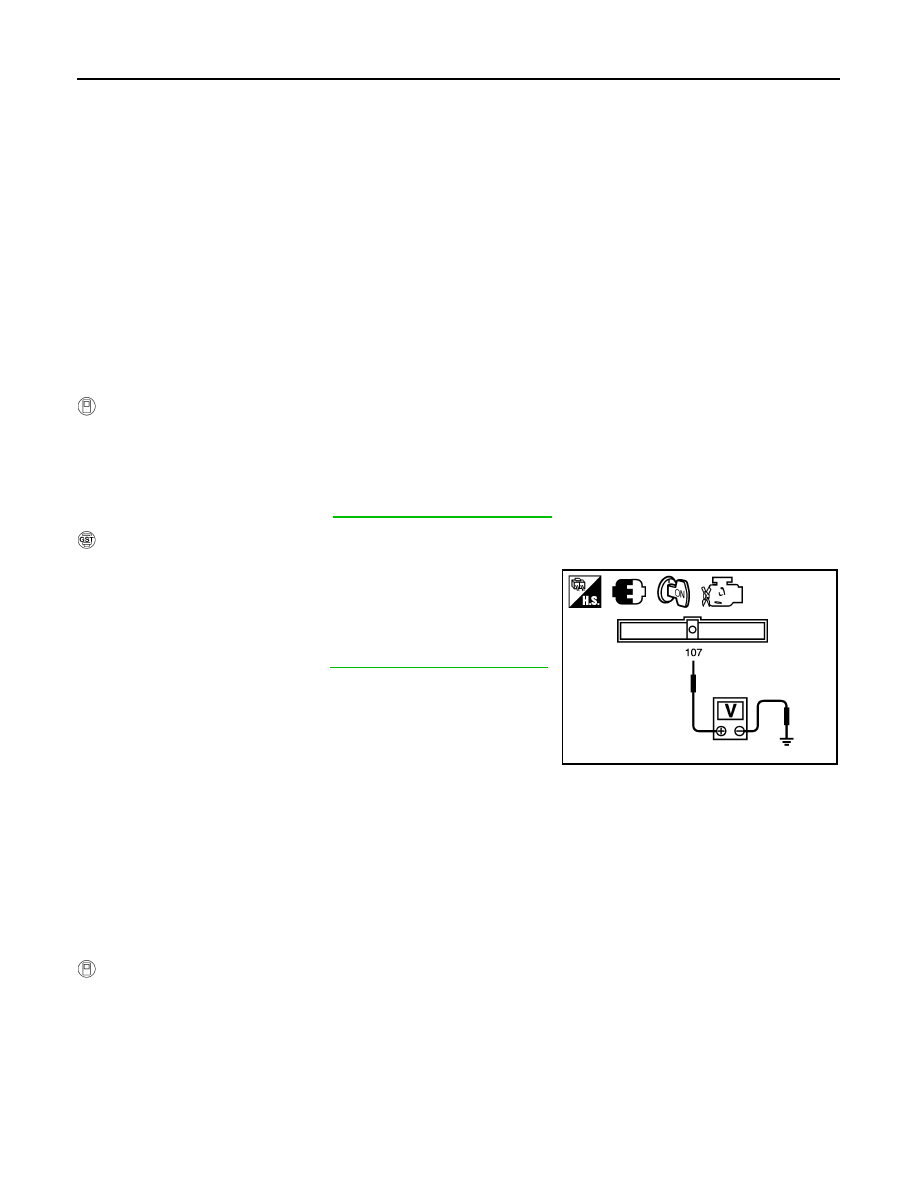
With GST
1. Turn ignition switch ON.
2. Set voltmeter probes to ECM terminal 107 (FTT sensor signal)
and ground.
3. Check that the voltage is 3.1 – 4.2 V.
4. Start engine and wait at least 60 seconds.
5. Check 1st trip DTC.
6. If 1st trip DTC is detected, go to
.
PROCEDURE FOR MALFUNCTION B
NOTE:
If DTC Confirmation Procedure has been previously conducted, always perform the following before conduct-
ing the next step.
1. Turn ignition switch OFF and wait at least 10 seconds.
2. Turn ignition switch ON.
3. Turn ignition switch OFF and wait at least 10 seconds.
TESTING CONDITION:
Always perform test at a temperature of 5
°C (41°F) or more.
With CONSULT-III
1. Start engine and warm it up to normal operating temperature.
2. Turn ignition switch OFF and wait at least 10 seconds.
3. Turn ignition switch ON.
4. Turn ignition switch OFF and wait at least 10 seconds.
5. Turn ignition switch ON.
6. Select “PURG VOL CN/V P1444” of “EVAPORATIVE SYSTEM” in “DTC WORK SUPPORT” mode with
CONSULT-III.
7. Touch “START”.
JMBIA2925ZZ

P0443 EVAP CANISTER PURGE VOLUME CONTROL SOLENOID VALVE
EC-227
< COMPONENT DIAGNOSIS >
[VK56DE]
C
D
E
F
G
H
I
J
K
L
M
A
EC
N
P
O
8. Start engine and let it idle until “TESTING” on CONSULT-III changes to “COMPLETED”. (It will take
approximately 10 seconds.)
If “TESTING” is not displayed after 5 minutes, retry from step 2.
9. Make sure that “OK” is displayed after touching “SELF-DIAG RESULTS”. If “NG” is displayed, refer to
With GST
1. Start engine and warm it up to normal operating temperature.
2. Turn ignition switch OFF and wait at least 10 seconds.
3. Turn ignition switch ON.
4. Turn ignition switch OFF and wait at least 10 seconds.
5. Start engine and let it idle for at least 20 seconds.
6. Select Service $07 with GST.
7. If 1st trip DTC is detected, go to
Diagnosis Procedure
INFOID:0000000005149245
1.
CHECK EVAP CANISTER PURGE VOLUME CONTROL SOLENOID VALVE POWER SUPPLY CIRCUIT
1. Turn ignition switch OFF.
2. Disconnect EVAP canister purge volume control solenoid valve
harness connector.
3. Turn ignition switch ON.
4. Check voltage between EVAP canister purge volume control
solenoid valve terminal 1 and ground with CONSULT-III or
tester.
OK or NG
OK
>> GO TO 3.
NG
>> GO TO 2.
2.
DETECT MALFUNCTIONING PART
Check the following.
• Harness connectors E2, F32
• Harness for open or short between EVAP canister purge volume control solenoid valve and IPDM E/R
• Harness for open or short between EVAP canister purge volume control solenoid valve and ECM
>> Repair harness or connectors.
3.
CHECK EVAP CANISTER PURGE VOLUME CONTROL SOLENOID VALVE OUTPUT SIGNAL CIRCUIT
FOR OPEN AND SHORT
1. Turn ignition switch OFF.
2. Disconnect ECM harness connector.
3. Check harness continuity between ECM terminal 45 and EVAP canister purge volume control solenoid
valve terminal 2. Refer to Wiring Diagram.
BBIA0366E
Voltage: Battery voltage
PBIB2245E
Continuity should exist.
Нет комментариевНе стесняйтесь поделиться с нами вашим ценным мнением.
Текст