Infiniti QX56 (JA60). Manual — part 481
EM-78
< REMOVAL AND INSTALLATION >
ENGINE ASSEMBLY
REMOVAL AND INSTALLATION
ENGINE ASSEMBLY
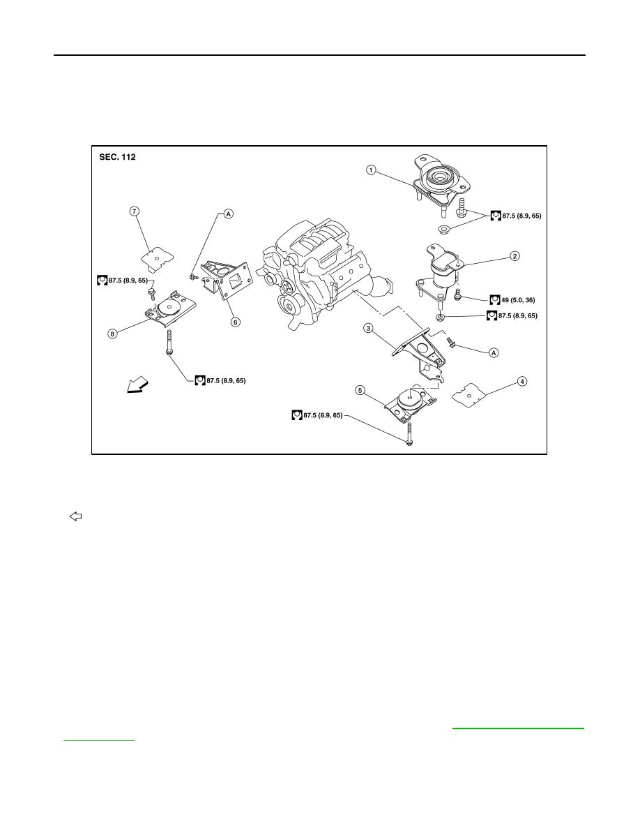
Exploded View
INFOID:0000000005149012
Removal and Installation
INFOID:0000000005149013
WARNING:
• Situate vehicle on a flat and solid surface.
• Place chocks at front and back of rear wheels.
• For engines not equipped with engine slingers, attach proper slingers and bolts described in PARTS
CATALOG.
CAUTION:
• Always be careful to work safely, avoid forceful or uninstructed operations.
• Do not start working until exhaust system and engine coolant are cooled sufficiently.
• If items or work required are not covered by the engine section, follow the applicable procedures.
• Always use the support point specified for lifting.
• Use either 2-point lift type or separate type lift. If board-on type is used for unavoidable reasons,
support at the rear axle jacking point with transmission jack or similar tool before starting work, in
preparation for the backward shift of center of gravity.
• For supporting points for lifting and jacking point at rear axle, refer to
REMOVAL
Preparation
1.
Rear engine mounting insulator 4WD 2.
Rear engine mounting insulator 2WD 3.
LH engine mounting bracket
4.
LH heat shield plate
5.
LH engine mounting insulator
6.
RH engine mounting bracket
7.
RH heat shield plate
8.
RH engine mounting insulator
A. Refer to Installation
Front
AWBIA0817GB
ENGINE ASSEMBLY
EM-79
< REMOVAL AND INSTALLATION >
C
D
E
F
G
H
I
J
K
L
M
A
EM
N
P
O
1. Release the fuel pressure. Refer to
.
2. Drain the engine coolant. Refer to
CO-11, "Changing Engine Coolant"
3. Drain the engine oil. Refer to
.
4. Partially drain the A/T fluid. Refer to
TM-150, "Changing the A/T Fluid (ATF)"
5. Disconnect the battery negative and positive terminal. Refer to
PG-74, "Removal and Installation"
.
6. Remove the engine hood. Refer to
DLK-234, "Removal and Installation of Hood Assembly"
7. Remove the cowl extension. Refer to
EXT-18, "Removal and Installation"
8. Remove the engine room cover using power tools.
9. Remove the air duct and air cleaner case assembly. Refer to
EM-25, "Removal and Installation"
.
10. Disconnect the vacuum hose between the vehicle and engine and set it aside.
11. Remove the radiator assembly and hoses. Refer to
CO-15, "Removal and Installation"
.
12. Remove the drive belt. Refer to
EM-13, "Removal and Installation"
.
13. Remove the fan blade. Refer to
CO-18, "Removal and Installation (Crankshaft Driven Type)"
14. Disconnect the engine room harness from the fuse box and set it aside.
15. Disconnect the ECM.
16. Disconnect the engine room harness from the engine side and set it aside.
17. Disconnect the engine harness grounds.
18. Disconnect the power steering reservoir tank from the engine and move it aside.
19. Disconnect the power steering oil pump from the engine. Move it aside and secure it using suitable wire or
ST-26, "Removal and Installation"
20. Remove the A/C compressor bolts and set the compressor aside. Refer to
(ATC).
21. Disconnect the brake booster vacuum line.
22. Disconnect the EVAP line.
23. Disconnect the fuel hose at the engine side connection. Refer to
EM-40, "Removal and Installation"
.
24. Disconnect the heater hoses at the cowl, and install plugs to avoid leakage of engine coolant.
25. Remove the A/T oil level indicator and indicator tube upper bolts.
26. Remove the front final drive assembly (4WD only). Refer to
DLN-215, "Removal and Installation"
27. Remove the exhaust manifolds. Refer to
EM-30, "Removal and Installation"
.
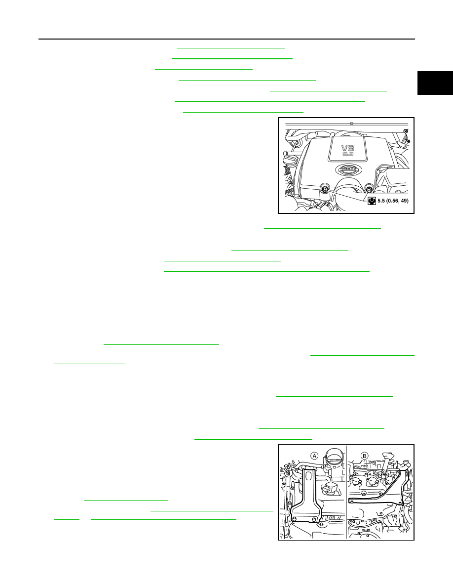
28. Install the engine slingers into the left bank cylinder head and
right bank cylinder head.
29. Disconnect and remove the crankshaft position sensor (POS).
30. Remove the A/T. Refer to
TM-186, "Removal and Installation
TM-188, "Removal and Installation (4WD)"
31. Lift using a hoist and secure the engine in position.
32. Remove the engine assembly from the vehicle, avoid interfer-
ence with the vehicle body.
CAUTION:
WBIA0795E
Engine slinger torque:
45.0 N·m (4.6 kg-m, 33 ft-lb)
WBIA0715E

EM-80
< REMOVAL AND INSTALLATION >
ENGINE ASSEMBLY
• Before and during lifting, always check if any harnesses are left connected.
33. Remove the parts that may restrict installation of the engine to the engine stand.
NOTE:
This procedure is described assuming that you use an engine stand mounting to the surface to which the
transmission mounts.
a. Before removing the drive plate, put a match mark (A) on the
crankshaft and drive plate for alignment during installation.
b. Remove the drive plate.
• Holding the crankshaft pulley bolt, lock the crankshaft to remove the drive plate bolts.
• Loosen the bolts diagonally.
CAUTION:
• Be careful not to damage the drive plate. Especially
avoid deforming and damaging of the signal plate teeth
(circumference position).
• Place the drive plate with the signal plate surface facing
other than downward.
• Keep magnetic materials away from the signal plate.
CAUTION:
Use an engine stand that has a load capacity [approximately 240kg (529 lb) or more] large enough
for supporting the engine weight.
• If the load capacity of the stand is not adequate, remove the following parts beforehand to
reduce the potential risk of overturning the stand.
- Remove the fuel tube and fuel injector assembly. Refer to
EM-40, "Removal and Installation"
- Remove the intake manifold. Refer to
EM-26, "Removal and Installation"
- Remove the ignition coil. Refer to
EM-37, "Removal and Installation"
.
- Remove the rocker cover. Refer to
EM-38, "Removal and Installation"
.
- Other removable brackets.
CAUTION:
Before removing the hanging chains, make sure the engine stand is stable and there is no risk of
overturning.
34. Remove the generator, if necessary. Refer to
CHG-21, "Removal and Installation"
35. Remove the engine mounting insulator and bracket using power tool, if necessary.
INSTALLATION
Installation is in the reverse order of removal.
ALBIA0522ZZ
KBIA2491E

ENGINE ASSEMBLY
EM-81
< REMOVAL AND INSTALLATION >
C
D
E
F
G
H
I
J
K
L
M
A
EM
N
P
O
• Tighten engine mounting bracket bolts in numerical order as
shown.
CAUTION:
• When replacing an engine or transmission you must make sure the dowels are installed correctly
during re-assembly.
• Improper alignment caused by missing dowels may cause vibration, oil leaks or breakage of driv-
etrain components.
INSPECTION AFTER INSTALLATION
• Before starting the engine, check oil/fluid levels including engine coolant and engine oil. If the levels are
lower than required quantity, fill to the specified level. Refer to
MA-13, "Fluids and Lubricants"
• Use procedure below to check for fuel leakage.
• Turn ignition switch ON (with engine stopped). With fuel pressure applied to the fuel piping, check for fuel
leakage at the connection points.
• Start engine. With engine speed increased, check again for fuel leakage at connection points.
• Run engine to check for unusual noise and vibration.
NOTE:
If hydraulic pressure inside timing chain tensioner drops after removal and installation, slack in the guide
may generate a pounding noise during and just after engine start. However, this is normal. Noise will stop
after hydraulic pressure rises.
• Warm up engine thoroughly to make sure there is no leakage of fuel, exhaust gas, or any oils/fluids including
engine oil and engine coolant.
• Bleed air from passages in lines and hoses, such as in cooling system.
• After cooling down the engine, again check oil/fluid levels including engine oil and engine coolant. Refill to
specified level if necessary.
• Summary of the inspection items:
*Transmission/transaxle/CVT fluid, power steering fluid, brake fluid, etc.
Engine mounting bracket
bolts
: 49 N·m (5.0 kg-m, 36 ft-lb)
AWBIA0820ZZ
Item
Before starting engine
Engine running
After engine stopped
Engine coolant
Level
Leakage
Level
Engine oil
Level
Leakage
Level
Other oils and fluids*
Level
Leakage
Level
Fuel
Leakage
Leakage
Leakage
Exhaust gas
—
Leakage
—
Нет комментариевНе стесняйтесь поделиться с нами вашим ценным мнением.
Текст