Infiniti QX56 (JA60). Manual — part 90
AV-168
< PREPARATION >
[AUDIO SYSTEM]
PREPARATION
PREPARATION
PREPARATION
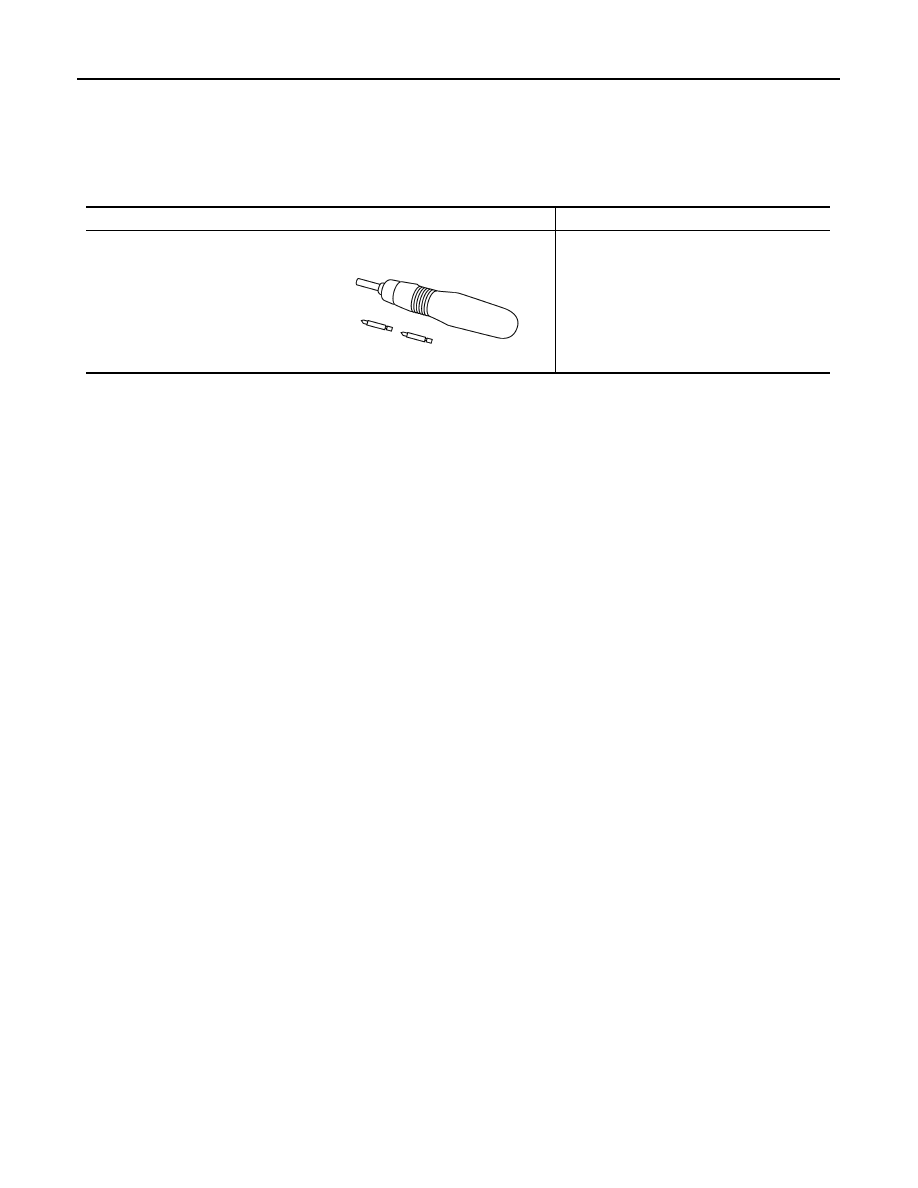
Commercial Service Tools
INFOID:0000000005146355
Tool name
Description
Power tool
Loosening bolts and nuts
PBIC0191E
AV
AV CONTROL UNIT
AV-169
< ON-VEHICLE REPAIR >
[AUDIO SYSTEM]
C
D
E
F
G
H
I
J
K
L
M
B
A
O
P
ON-VEHICLE REPAIR
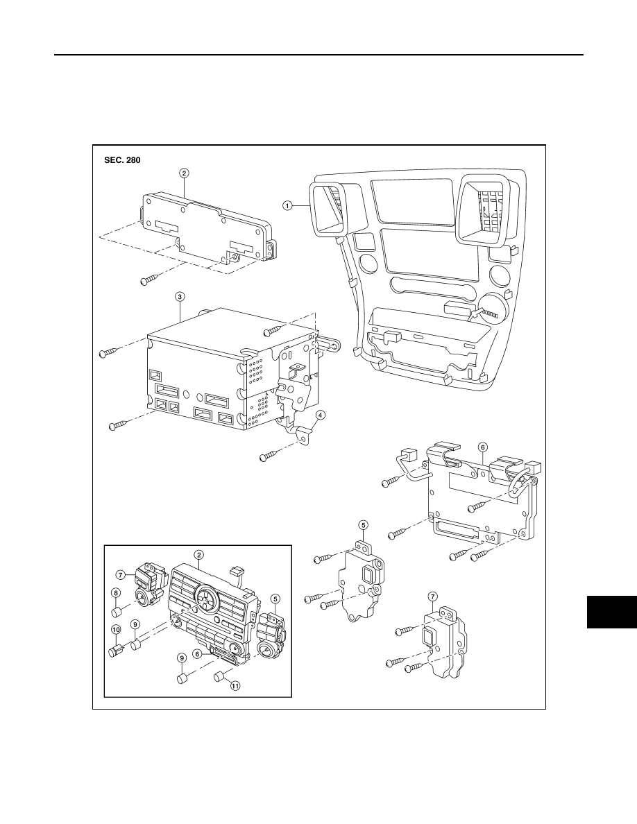
AV CONTROL UNIT
Removal and Installation
INFOID:0000000005146356
CAUTION:
1.
Cluster lid C
2.
AV switch
3.
AV control unit
4.
AV control unit brackets
5.
Tuner knob switch
6.
A/C and AV switch assembly
7.
Volume knob switch
8.
Volume knob
9.
Temp knobs RH and LH
10. Enter button
11. Tuner knob
ALNIA0201ZZ
AV-170
< ON-VEHICLE REPAIR >
[AUDIO SYSTEM]
AV CONTROL UNIT
Only remove and replace the A/C or AV switch assembly knobs if damaged or missing. The knobs
must not be removed from the switches when removing and installing the A/C or AV switch assembly
to prevent damage to the switch assembly.
REMOVAL
1. Disconnect the battery negative terminal.
2. Remove the cluster lid C. Refer to
IP-15, "Removal and Installation"
.
3. Remove the AV control unit screws, using a power tool.
4. Remove the AV control unit.
5. Remove the A/C and AV switch assembly screws, then remove the A/C and AV switch assembles as nec-
essary.
INSTALLATION
Installation is in the reverse order of removal.
AV
DISPLAY UNIT
AV-171
< ON-VEHICLE REPAIR >
[AUDIO SYSTEM]
C
D
E
F
G
H
I
J
K
L
M
B
A
O
P
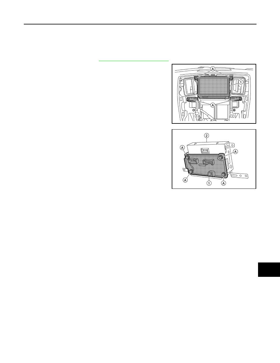
DISPLAY UNIT
Removal and Installation
INFOID:0000000005146357
REMOVAL
1. Remove cluster lid C. Refer to
IP-15, "Removal and Installation"
2. Remove the display unit screws (A), pull out the display unit (1)
from instrument panel, to disconnect the display unit connectors.
3. Remove the A/C auto amp. screws (A) and the A/C auto amp.
(1).
• Display unit (2)
4. Remove the display unit bracket screws and the display unit
brackets.
INSTALLATION
Installation is in the reverse order of removal.
ALNIA0272ZZ
ALIIA0063ZZ
Нет комментариевНе стесняйтесь поделиться с нами вашим ценным мнением.
Текст