Infiniti QX56 (JA60). Manual — part 695
MWI
METER SYSTEM
MWI-15
< FUNCTION DIAGNOSIS >
C
D
E
F
G
H
I
J
K
L
M
B
A
O
P
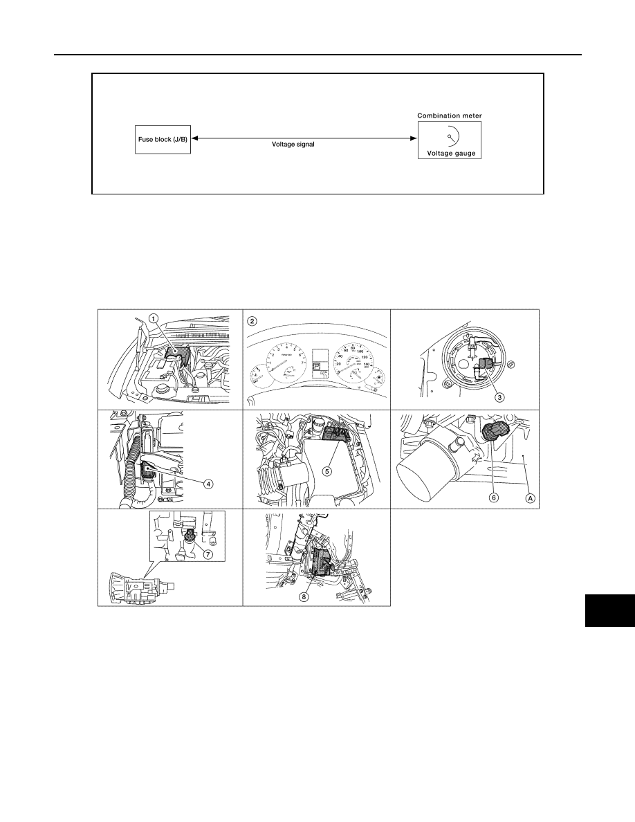
VOLTAGE GAUGE : System Diagram
INFOID:0000000005146050
VOLTAGE GAUGE : System Description
INFOID:0000000005146051
The voltage gauge indicates the battery/charging system voltage.
The voltage gauge is regulated by the unified meter control unit.
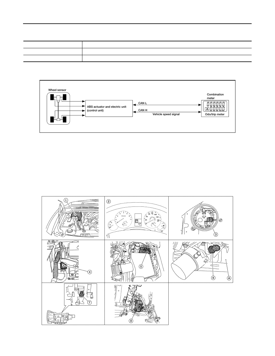
VOLTAGE GAUGE : Component Parts Location
INFOID:0000000005146052
AWNIA0106GB
1.
IPDM E/R E122, E124
2.
Combination meter M23, M24
3.
Fuel level sensor unit and fuel pump
C5 (view with inspection hole cover re-
moved)
4.
ECM E16 (view with battery removed) 5.
ABS actuator and electric unit (control
unit) E125
6.
Oil pressure switch F4
A: Oil pan (upper)
7.
A/T assembly F9
8.
BCM M18, M19 (view with instrument
lower panel LH removed)
AWNIA0201ZZ
MWI-16
< FUNCTION DIAGNOSIS >
METER SYSTEM
VOLTAGE GAUGE : Component Description
INFOID:0000000005146053
ODO/TRIP METER
ODO/TRIP METER : System Diagram
INFOID:0000000005146054
ODO/TRIP METER : System Description
INFOID:0000000005146055
The vehicle speed signal and the memory signals from the meter memory circuit are processed by the combi-
nation meter and the mileage is displayed.
HOW TO CHANGE THE DISPLAY FOR ODO/TRIP METER
Refer to Owner's Manual for odo/trip meter operating instructions.
ODO/TRIP METER : Component Parts Location
INFOID:0000000005146056
Unit
Description
Combination meter
Indicates the battery voltage according to the voltage signal received from the fuse block (J/B).
Fuse block (J/B)
Transmits the battery voltage signal to the combination meter.
AWNIA0005GB
AWNIA0201ZZ
MWI
METER SYSTEM
MWI-17
< FUNCTION DIAGNOSIS >
C
D
E
F
G
H
I
J
K
L
M
B
A
O
P
ODO/TRIP METER : Component Description
INFOID:0000000005146057
SHIFT POSITION INDICATOR
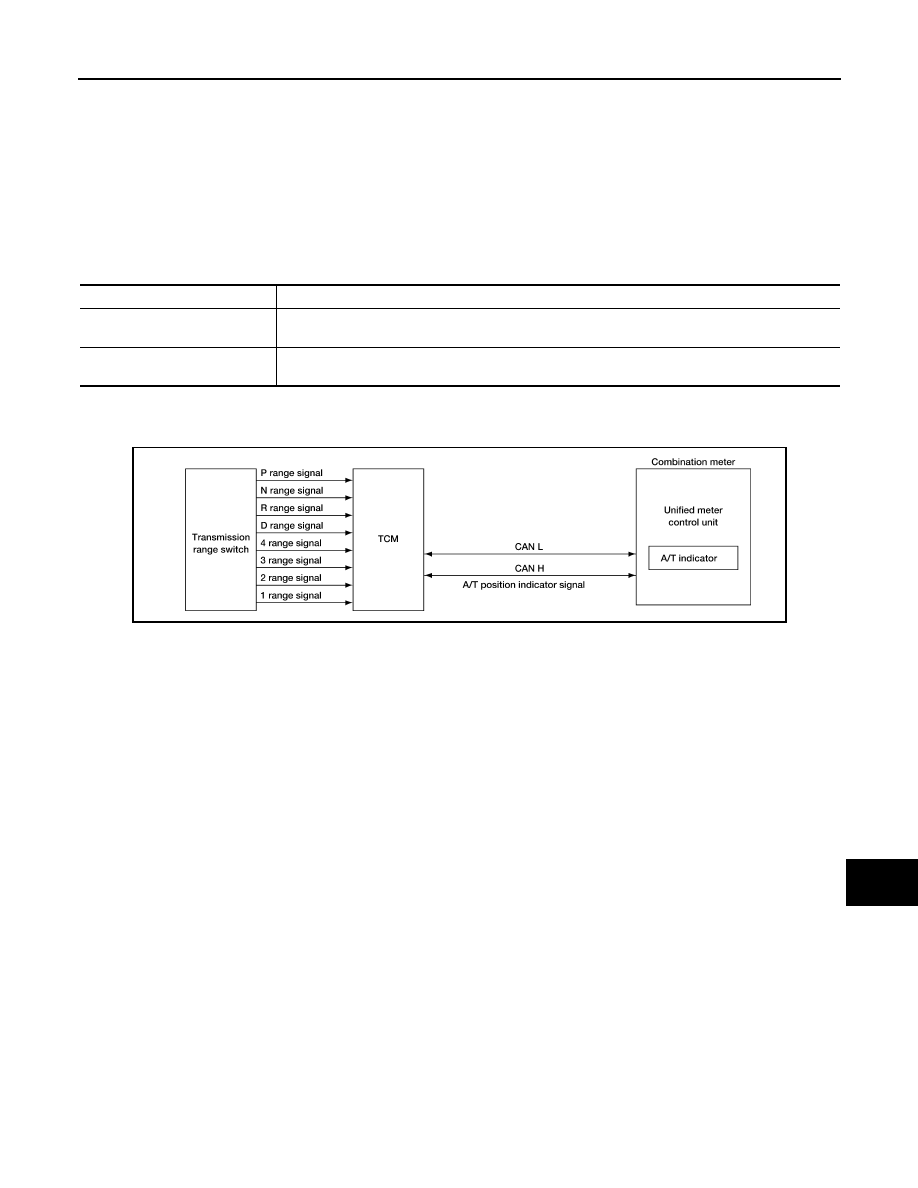
SHIFT POSITION INDICATOR : System Diagram
INFOID:0000000005146058
SHIFT POSITION INDICATOR : System Description
INFOID:0000000005146059
The TCM receives A/T indicator signals from the transmission range switch. The TCM then sends A/T position
indicator signals to the combination meter via CAN communication lines. The combination meter indicates the
received shift position.
1.
IPDM E/R E122, E124
2.
Combination meter M23, M24
3.
Fuel level sensor unit and fuel pump
C5 (view with inspection hole cover re-
moved)
4.
ECM E16 (view with battery removed) 5.
ABS actuator and electric unit (control
unit) E125
6.
Oil pressure switch F4
A: Oil pan (upper)
7.
A/T assembly F9
8.
BCM M18, M19 (view with instrument
lower panel LH removed)
Unit
Description
Combination meter
Converts the vehicle speed signal received from the ABS actuator and electric unit (control unit) via
CAN communication to mileage, and it displays the accumulated mileage to the odo/trip meter.
ABS actuator and electric unit
(control unit)
Transmits the vehicle speed signal to the combination meter via CAN communication.
AWNIA1906GB
MWI-18
< FUNCTION DIAGNOSIS >
METER SYSTEM
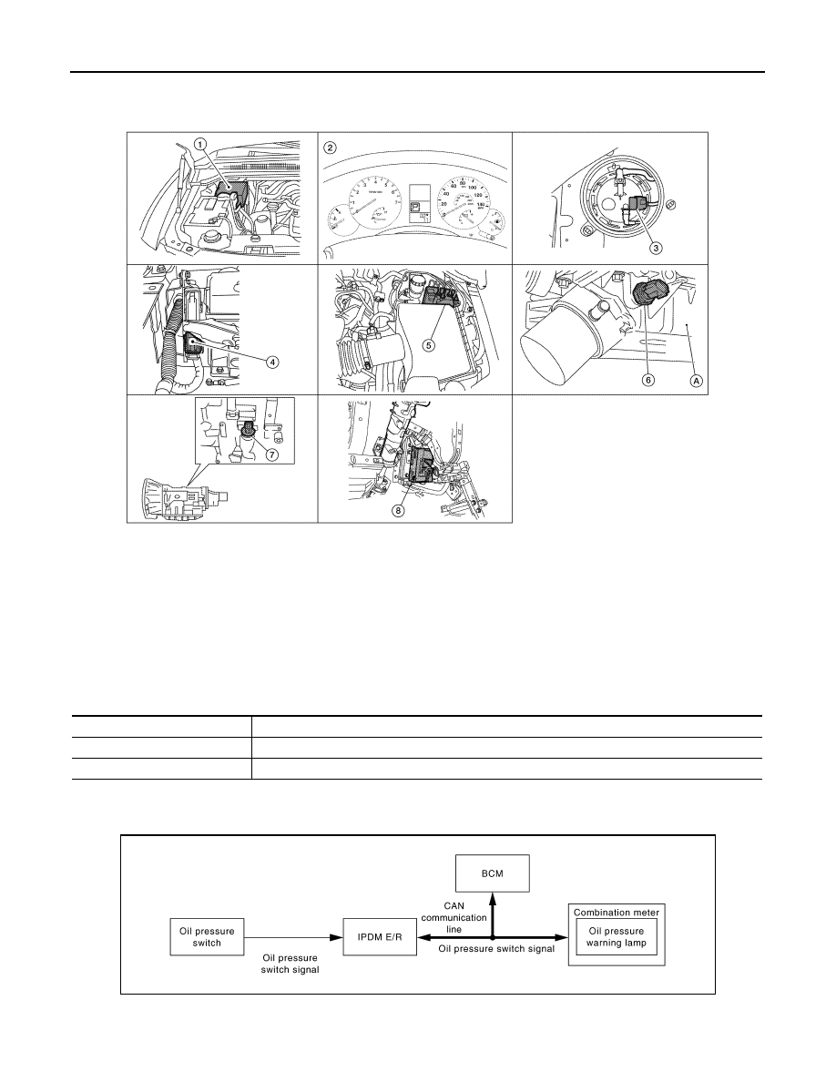
SHIFT POSITION INDICATOR : Component Parts Location
INFOID:0000000005146060
SHIFT POSITION INDICATOR : Component Description
INFOID:0000000005146061
WARNING LAMPS/INDICATOR LAMPS
WARNING LAMPS/INDICATOR LAMPS : System Diagram
INFOID:0000000005146062
1.
IPDM E/R E122, E124
2.
Combination meter M23, M24
3.
Fuel level sensor unit and fuel pump
C5 (view with inspection hole cover re-
moved)
4.
ECM E16 (view with battery removed) 5.
ABS actuator and electric unit (control
unit) E125
6.
Oil pressure switch F4
A: Oil pan (upper)
7.
A/T assembly F9
8.
BCM M18, M19 (view with instrument
lower panel LH removed)
AWNIA0201ZZ
Unit
Description
Combination meter
Displays the shift position on the information display using shift position signal received from TCM.
TCM
Transmits the shift position signal to the combination meter via CAN communication.
JSNIA0449GB
Нет комментариевНе стесняйтесь поделиться с нами вашим ценным мнением.
Текст