Infiniti QX56 (JA60). Manual — part 954
TM-118
< ECU DIAGNOSIS >
TCM
Even when the electronic circuits are normal, under special conditions (for example, when slamming on the
brake with the wheels spinning drastically and stopping the tire rotation), the transmission can go into fail-safe
mode. If this happens, switch “OFF” the ignition switch for 10 seconds, then switch it “ON” again to return to
the normal shift pattern. Therefore, the customer's vehicle has returned to normal, so handle according to the
“diagnostics flow” (Refer to
FAIL-SAFE FUNCTION
If any malfunction occurs in a sensor or solenoid, this function controls the A/T to mark driving possible.
Output Speed Sensor
• Signals are input from two systems - from output speed sensor installed on the transmission and from com-
bination meter so normal driving is possible even if there is a malfunction in one of the systems. And if output
speed sensor has unusual cases, 5GR is prohibited.
Accelerator Pedal Position Sensor
• If there is a malfunction in one of the systems, the accelerator opening angle is controlled by ECM according
to a pre-determined accelerator angle to make driving possible. And if there are malfunctions in tow sys-
tems, the engine speed is fixed by ECM to a pre-determined engine speed to make driving possible.
Throttle Position Sensor
• If there is a malfunction in one of the systems, the accelerator opening angle is controlled by ECM according
to a pre-determined accelerator angle to make driving possible. And if there are malfunctions in tow sys-
tems, the accelerator opening angle is controlled by the idle signal sent from the ECM which is based on
input indicating either idle condition or off-idle condition (pre-determined accelerator opening) in order to
make driving possible.
Transmission Range Switch
• In the unlikely event that a malfunction signal enters the TCM, the position indicator is switched “OFF”, the
starter relay is switched “OFF” (starter starting is disabled), the back-up lamp relay switched “OFF” (back-up
lamp is OFF) and the position is fixed to the “D” position to make driving possible.
Starter Relay
• The starter relay is switched “OFF”. (Starter starting is disabled.)
Interlock
• If there is an interlock judgment malfunction, the transmission is fixed in 2GR to make driving possible.
NOTE:
When the vehicle is driven fixed in 2GR, a input speed sensor malfunction is displayed, but this is
not a input speed sensor malfunction.
• When the interlock is detected at the 3GR or more, it is locked at the 2GR.
1st Engine Braking
• When there is an 1st engine brake judgment malfunction, the low coast brake solenoid is switched “OFF” to
avoid the engine brake operation.
Line Pressure Solenoid
• The solenoid is switched “OFF” and the line pressure is set to the maximum hydraulic pressure to make driv-
ing possible.
Torque Converter Clutch Solenoid
• The solenoid is switched “OFF” to release the lock-up.
Low Coast Brake Solenoid
• When a (electrical or functional) malfunction occurs, in order to make driving possible, the engine brake is
not applied in 1GR and 2GR.
Input Clutch Solenoid
• If a (electrical or functional) malfunction occurs with the solenoid either “ON” or “OFF”, the transmission is
held in 4GR to make driving possible.
Direct Clutch Solenoid
• If a (electrical or functional) malfunction occurs with the solenoid either “ON” or “OFF”, the transmission is
held in 4GR to make driving possible.
Front Brake Solenoid
• If a (electrical or functional) malfunction occurs with the solenoid “ON”, in order to make driving possible, the
A/T is held in 5GR; if the solenoid is OFF, 4GR.
TCM
TM-119
< ECU DIAGNOSIS >
C
E
F
G
H
I
J
K
L
M
A
B
TM
N
O
P
High and Low Reverse Clutch Solenoid
• If a (electrical or functional) malfunction occurs with the solenoid either “ON” or “OFF”, the transmission is
held in 4GR to make driving possible.
Input Speed Sensor 1 or 2
• The control is the same as if there were no input speed sensors, 5GR is prohibited.
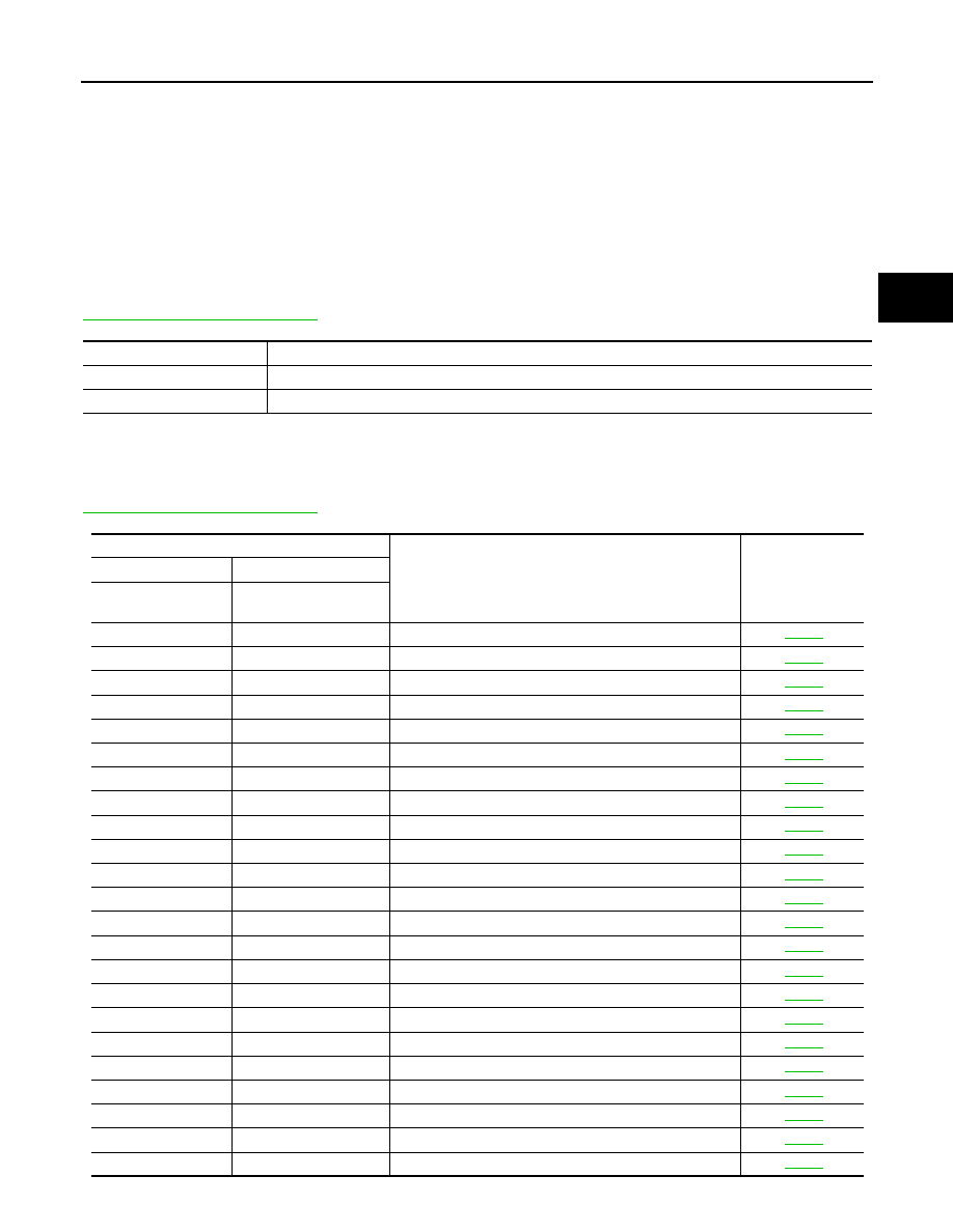
DTC Inspection Priority Chart
INFOID:0000000005148691
If some DTCs are displayed at the same time, perform inspections one by one based on the following priority
chart.
NOTE:
If DTC U1000 is displayed with other DTCs, first perform the trouble diagnosis for DTC U1000. Refer to
.
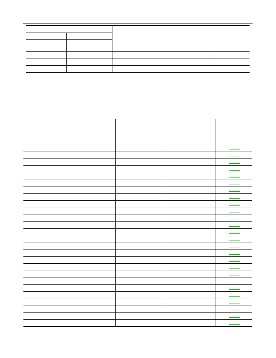
DTC No. Index
INFOID:0000000005148692
NOTE:
If DTC U1000 is displayed with other DTC, first perform the trouble diagnosis for DTC U1000. Refer to
.
Priority
Detected items (DTC)
1
U1000 CAN COMM CIRCUIT
2
Except above
DTC
Items
(CONSULT- III screen terms)
Reference
OBD- II
Except OBD- II
CONSULT- III
GST (*1)
CONSULT- III only
“TRANSMISSION”
—
P0615
STARTER RELAY
P0700
P0700
TRANSMISSION CONTROL
P0705
P0705
T/M RANGE SWITCH A
P0710
P1710
FLUID TEMP SENSOR
P0717
P0717
INPUT SPEED SENSOR A
P0720
P0720
OUTPUT SPEED SENSOR
—
P0725
ENGINE SPEED
P0731
P0731
1GR INCORRECT RATIO
P0732
P0732
2GR INCORRECT RATIO
P0733
P0733
3GR INCORRECT RATIO
P0734
P0734
4GR INCORRECT RATIO
P0735
P0735
5GR INCORRECT RATIO
P0740
P0740
TORQUE CONVERTER
P0744 P0744
TORQUE
CONVERTER
P0745
P0745
PC SOLENOID A
—
P1705
TP SENSOR
—
P1721
VEHICLE SPEED SIGNAL
P1730
P1730
INTERLOCK
—
P1731
1GR E/BRAKING
P1752
P1752
INPUT CLUTCH SOLENOID
P1757
P1757
FR BRAKE SOLENOID
P1762
P1762
DRCT CLUTCH SOLENOID
P1767
P1767
HLR CLUTCH SOLENOID
TM-120
< ECU DIAGNOSIS >
TCM
*1: These numbers are prescribed by SAE J2012.
*2: These malfunctions cannot be displayed MIL if another malfunction is assigned to MIL.
DTC Alphabetical Index
INFOID:0000000005148693
NOTE:
If DTC U1000 is displayed with other DTC, first perform the trouble diagnosis for DTC U1000. Refer to
.
*1: These numbers are prescribed by SAE J2012.
*2: These malfunctions cannot be displayed MIL if another malfunction is assigned to MIL.
P1772
P1772
L C BRAKE SOLENOID
P1774 (2*)
P1774
L C BRAKE SOLENOID
U1000
U1000
CAN COMM CIRCUIT
DTC
Items
(CONSULT- III screen terms)
Reference
OBD- II
Except OBD- II
CONSULT- III
GST (*1)
CONSULT- III only
“TRANSMISSION”
Items
(CONSULT- III screen terms)
DTC
Reference
OBD- II
Except OBD- II
CONSULT- III GST (*1)
CONSULT- III only “TRANS-
MISSION”
1ST E/BRAKING
—
P1731
1GR INCORRECT RATIO
P0731
P0731
2GR INCORRECT RATIO
P0732
P0732
3GR INCORRECT RATIO
P0733
P0733
4GR INCORRECT RATIO
P0734
P0734
5GR INCORRECT RATIO
P0735
P0735
INTERLOCK
P1730
P1730
TORQUE CONVERTER
P0744
P0744
FLUID TEMP SENSOR
P0710
P1710
CAN COMM CIRCUIT
U1000
U1000
DRCT CLUTCH SOLENOID
P1762
P1762
ENGINE SPEED
—
P0725
FR BRAKE SOLENOID
P1757
P1757
HLR CLUTCH SOLENOID
P1767
P1767
INPUT CLUTCH SOLENOID
P1752
P1752
PC SOLENOID A
P0745
P0745
L C BRAKE SOLENOID
P1772
P1772
L C BRAKE SOLENOID
P1774
P1774
T/M RANGE SWITCH A
P0705
P0705
STARTER RELAY
—
P0615
TORQUE CONVERTER
P0740
P0740
TRANSMISSION CONTROL
P0700
P0700
TP SENSOR
—
P1705
INPUT SPEED SENSOR A
P0717
P0717
VEHICLE SPEED SIGNAL
—
P1721
OUTPUT SPEED SENSOR
P0720
P0720
SYSTEM SYMPTOM
TM-121
< SYMPTOM DIAGNOSIS >
C
E
F
G
H
I
J
K
L
M
A
B
TM
N
O
P
SYMPTOM DIAGNOSIS
SYSTEM SYMPTOM
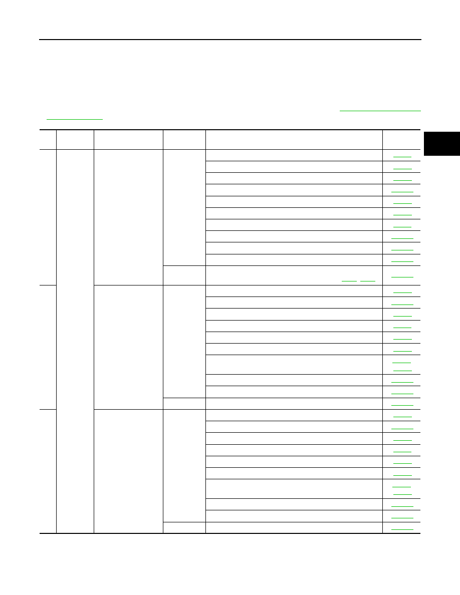
Symptom Table
INFOID:0000000005148715
• The diagnostics item numbers show the sequence for inspection. Inspect in order from item 1.
• Overhaul and inspect inside the A/T only if A/T fluid condition is NG. Refer to
No.
Items
Symptom
Condition
Diagnostic Item
Reference
page
1
Shift
Shock
Large shock. (“N”
→“
D” position)
ON vehicle
1. Engine idle speed
2. Engine speed signal
3. Accelerator pedal position sensor
4. Control cable adjustment
5. ATF temperature sensor
6. Front brake solenoid valve
7. CAN communication line
8. Fluid level and state
9. Line pressure test
10. Control valve with TCM
OFF vehicle
11. Forward brake (Parts behind drum support is impossible
to perform inspection by disassembly. Refer to
2
Shock is too large
when changing D
1
→
D
2
.
ON vehicle
1. Accelerator pedal position sensor
2. Control cable adjustment
3. Direct clutch solenoid valve
4. CAN communication line
5. Engine speed signal
6. Input speed sensor
7. Output speed sensor and vehicle speed signal
8. Fluid level and state
9. Control valve with TCM
OFF vehicle
10. Direct clutch
3
Shock is too large
when changing D
2
→
D
3
.
ON vehicle
1. Accelerator pedal position sensor
2. Control cable adjustment
3. High and low reverse clutch solenoid valve
4. CAN communication line
5. Engine speed signal
6. Input speed sensor
7. Output speed sensor and vehicle speed signal
8. Fluid level and state
9. Control valve with TCM
OFF vehicle
10. High and low reverse clutch
Нет комментариевНе стесняйтесь поделиться с нами вашим ценным мнением.
Текст