Infiniti QX56 (JA60). Manual — part 238

AUTOMATIC BACK DOOR SELF-DIAGNOSIS PROCEDURE
DLK-123
< COMPONENT DIAGNOSIS >
[WITH INTELLIGENT KEY SYSTEM]
C
D
E
F
G
H
I
J
L
M
A
B
DLK
N
O
P
AUTOMATIC BACK DOOR SELF-DIAGNOSIS PROCEDURE
Self-Diagnosis Procedure
INFOID:0000000005146997
INPUT SIGNAL CHECK MODE
Input signal check mode allows testing of switch input signal to the back door control unit.
To activate input signal check mode on the automatic sliding door, perform the following steps:
1. Turn ignition switch OFF.
2. Turn back door close switch to CANCEL (system cancelled).
3. Place A/T selector lever in P position.
4. Using the inside emergency release lever, open the back door.
5. Have an assistant press and hold the back door handle switch.
6. While the assistant continues to hold the back door handle switch, turn ignition switch ON (DO NOT start
engine).
7. After approximately 5 seconds, the back door warning chime will sound for 0.5 seconds.
8. Release the back door handle switch.
9. Within 8 seconds of the back door warning chime sounding, press and hold the power liftgate switch.
10. After approximately 5 seconds, the back door warning chime will sound for 1 second.
11. Release the power liftgate switch.
12. The input signal check mode is now initialized.
The input signal check mode can test the following inputs. The back door warning chime will sound for approx-
imately 0.5 second each time a switch signal input occurs. Use this test when one of these inputs is not
responding during normal automatic back door operation.
*Back door warning chime should sound as soon as vehicle moves.
Turn ignition switch OFF to end input signal check mode.
OPERATING CHECK MODE
Operating check mode allows self-diagnosis of the automatic back door system.
To activate operating check mode on the automatic back door, perform the following steps:
1. Turn ignition switch OFF.
2. Turn back door close switch to CANCEL (system cancelled).
3. Place A/T selector lever in P position.
4. Using the inside emergency release lever, open the back door.
5. Have an assistant press and hold the back door handle switch.
6. While the assistant continues to hold the back door handle switch, turn ignition switch ON (DO NOT start
engine).
7. After approximately 5 seconds, the back door warning chime will sound for 0.5 second.
8. Release the back door handle switch.
Switch signal
Operation
Refer to
Power liftgate switch
OFF
→ ON
Back door close switch (CLOSE)
OFF
→ ON
Back door close switch (CANCEL)
OFF
→ ON
Back door handle switch
OFF
→ ON
A/T shift selector (park position switch)
P position
→ other than P position
Vehicle speed*
Vehicle speed
Remote keyless entry signal
Keyfob switch OFF
→ ON
Door lock/unlock signal
LOCK
→ UNLOCK
Pinch strip LH signal
OFF
→ ON
Pinch strip RH signal
OFF
→ ON

DLK-124
< COMPONENT DIAGNOSIS >
[WITH INTELLIGENT KEY SYSTEM]
AUTOMATIC BACK DOOR SELF-DIAGNOSIS PROCEDURE
9. Within 8 seconds of the back door warning chime sounding, press the power liftgate switch 5 times in
rapid succession.
10. After approximately 5 seconds, the back door warning chime will sound for 1 second.
11. Release the power liftgate switch.
12. Immediately close the back door manually.
13. Press and release the power liftgate switch to activate the operating check mode.
Self-diagnosis results are indicated by the back door warning chime.
Turn ignition switch OFF to end input signal check mode.
Back door warning chime order
Back door warning chime length
Start self-diagnosis
1.5 seconds
OK
NG
1. Operating conditions diagnosis
0.5 second
0.2 second
2. Back door encoder diagnosis
0.5 second
0.2 second
3. Back door clutch diagnosis
0.5 second
0.2 second
4. Back door motor diagnosis
0.5 second
0.2 second
5. Cinch latch motor diagnosis
0.5 second
0.2 second
Restart self-diagnosis
1.5 seconds
Item
NG Result
Refer to
1. Operating conditions diagnosis result
One of the following operating conditions no
longer met: ignition switch ON, back door close
switch (CANCEL) ON, A/T selector lever in P
position
—
2. Back door encoder diagnosis result
Sensor diagnosis/short, pulse signal, pulse
signal direction
3. Back door clutch diagnosis result
Back door clutch does not operate
4. Back door motor diagnosis result
Back door motor does not operate (no operat-
ing current)
5. Cinch latch motor diagnosis result
Cinch latch motor does not operate (no operat-
ing current)
POWER LIFTGATE SWITCH FUNCTION
DLK-125
< COMPONENT DIAGNOSIS >
[WITH INTELLIGENT KEY SYSTEM]
C
D
E
F
G
H
I
J
L
M
A
B
DLK
N
O
P
POWER LIFTGATE SWITCH FUNCTION
Diagnosis Procedure
INFOID:0000000005146998
Regarding Wiring Diagram information, refer to
DLK-199, "Wiring Diagram—AUTOMATIC BACK DOOR SYS-
1.
POWER LIFTGATE SWITCH FUNCTION INSPECTION
Check power liftgate switch using switch operation.
Did the back door respond correctly?
YES
>> Power liftgate switch is OK.
NO
>> GO TO 2
2.
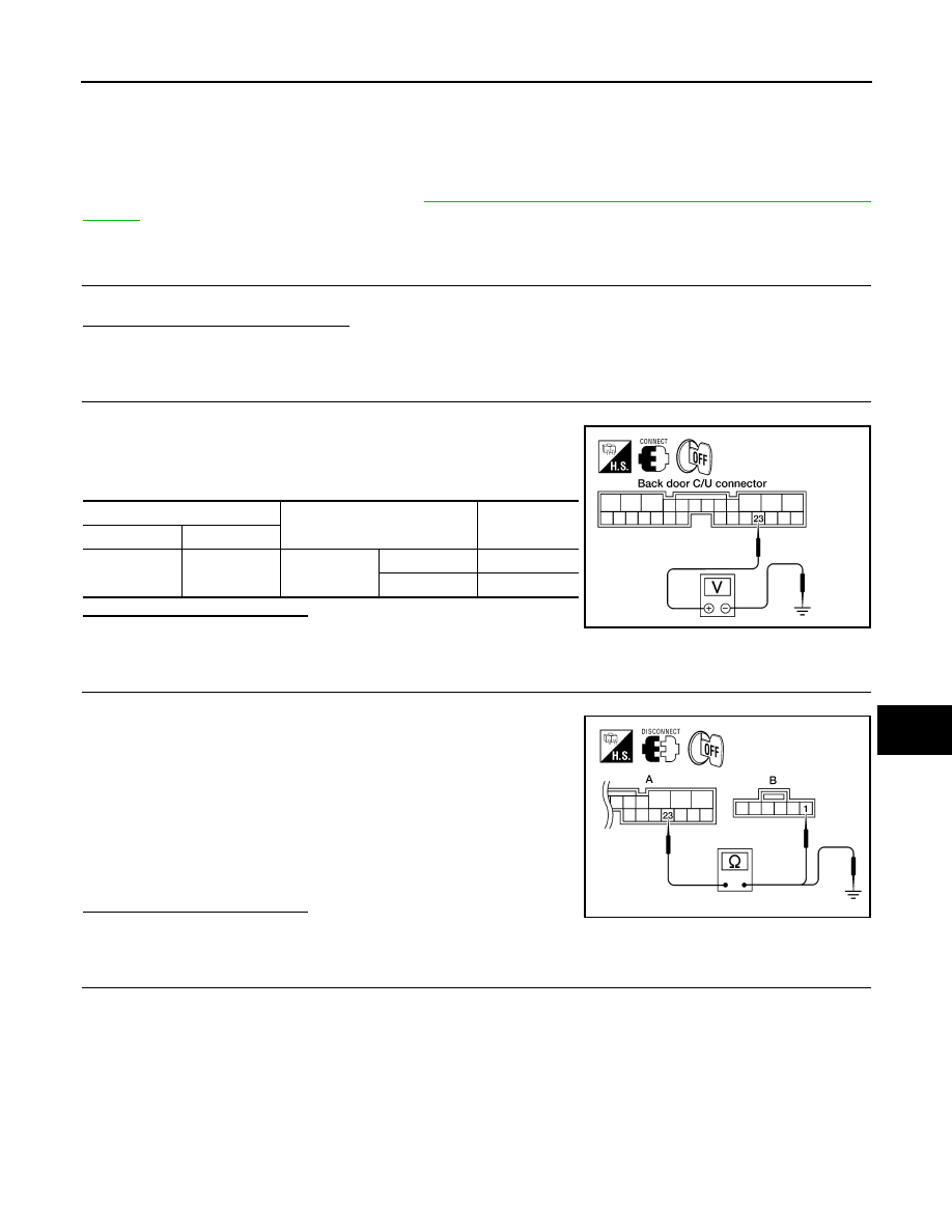
POWER LIFTGATE SWITCH SIGNAL INSPECTION
1. Turn ignition switch OFF.
2. While operating the power liftgate switch, check voltage
between back door control unit connector B55 terminal 23 and
ground.
Is the inspection result normal?
YES
>> Switch is OK.
NO
>> GO TO 3
3.
POWER LIFTGATE SWITCH CIRCUIT INSPECTION
1. Disconnect back door control unit and power liftgate switch connectors.
2. Check continuity between back door control unit connector (A)
B55 terminal 23 and power liftgate switch connector (B) M92 ter-
minal 1.
3. Check continuity between back door control unit connector (A)
B55 terminal 23 and ground.
Is the inspection result normal?
YES
>> GO TO 4
NO
>> Repair the harness between the power liftgate switch and the back door control unit.
4.
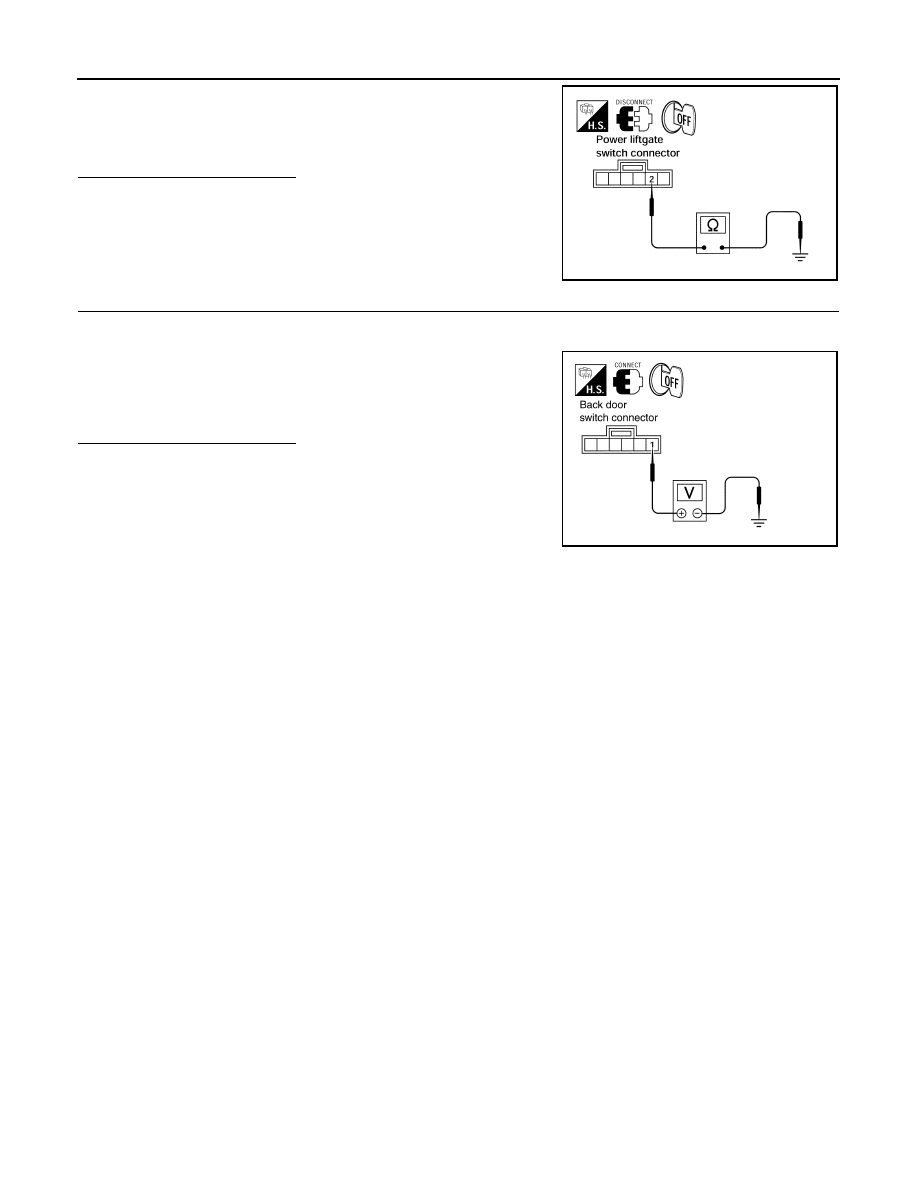
POWER LIFTGATE SWITCH GROUND INSPECTION
Terminal
Measuring condition
Voltage (V)
(Approx.)
(+)
(-)
23
Ground
Power liftgate
switch
ON
0
OFF
Battery voltage
LIIA0802E
23 - 1
: Continuity should exist.
23 - Ground
: Continuity should not exist.
ALKIA0670ZZ
DLK-126
< COMPONENT DIAGNOSIS >
[WITH INTELLIGENT KEY SYSTEM]
POWER LIFTGATE SWITCH FUNCTION
Check continuity between power liftgate switch connector terminal 2
and ground.
Is the inspection result normal?
YES
>> GO TO 5
NO
>> Repair the harness between the power liftgate switch
and ground.
5.
POWER LIFTGATE SWITCH POWER SUPPLY CIRCUIT INSPECTION
1. Reconnect back door control unit.
2. Ensure liftgate is closed.
3. Check voltage between power liftgate switch connector M92 ter-
minal 1 and ground.
Is the inspection result normal?
YES
>> Replace the power liftgate switch.
NO
>> Replace the back door control unit.
2 - Ground
: Continuity should exist.
LIIA1065E
1 - Ground
:Approx. battery voltage
LIIA1063E
Нет комментариевНе стесняйтесь поделиться с нами вашим ценным мнением.
Текст