Infiniti QX56 (JA60). Manual — part 429
EC-368
< COMPONENT DIAGNOSIS >
[VK56DE]
P2122, P2123 APP SENSOR
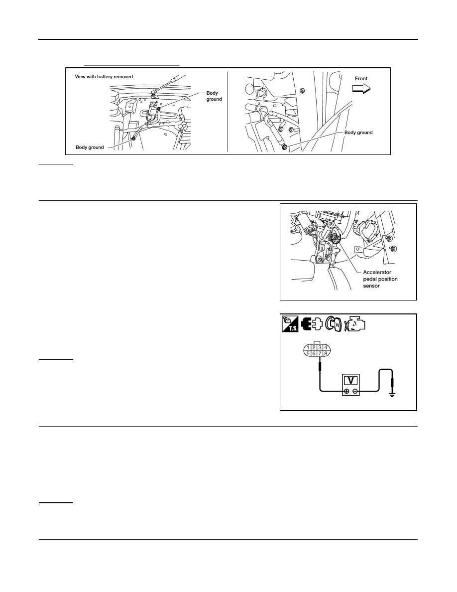
1. Turn ignition switch OFF.
2. Loosen and retighten three ground screws on the body.
OK or NG
OK
>> GO TO 2.
NG
>> Repair or replace ground connections.
2.
CHECK APP SENSOR 1 POWER SUPPLY CIRCUIT
1. Disconnect accelerator pedal position (APP) sensor harness
connector.
2. Turn ignition switch ON.
3. Check voltage between APP sensor terminal 7 and ground with
CONSULT-III or tester.
OK or NG
OK
>> GO TO 3.
NG
>> Repair open circuit or short to ground or short to power
in harness or connectors.
3.
CHECK APP SENSOR 1 GROUND CIRCUIT FOR OPEN AND SHORT
1. Turn ignition switch OFF.
2. Disconnect ECM harness connector.
3. Check harness continuity between ECM terminal 82 and APP sensor terminal 1.
Refer to Wiring Diagram.
4. Also check harness for short to ground and short to power.
OK or NG
OK
>> GO TO 4.
NG
>> Repair open circuit or short to ground or short to power in harness or connectors.
4.
CHECK APP SENSOR INPUT SIGNAL CIRCUIT FOR OPEN AND SHORT
1. Check harness continuity between ECM terminal 106 and APP sensor terminal 2.
Refer to Wiring Diagram.
BBIA0354E
BBIA0361E
Voltage: Approximately 5 V
JMBIA0601ZZ
Continuity should exist.
P2122, P2123 APP SENSOR
EC-369
< COMPONENT DIAGNOSIS >
[VK56DE]
C
D
E
F
G
H
I
J
K
L
M
A
EC
N
P
O
2. Also check harness for short to ground and short to power.
OK or NG
OK
>> GO TO 5.
NG
>> Repair open circuit or short to ground or short to power in harness or connectors.
5.
CHECK APP SENSOR
EC-369, "Component Inspection"
OK or NG
OK
>> GO TO 7.
NG
>> GO TO 6.
6.
REPLACE ACCELERATOR PEDAL ASSEMBLY
1. Replace the accelerator pedal assembly.
2. Perform
EC-18, "Accelerator Pedal Released Position Learning"
3. Perform
EC-18, "Throttle Valve Closed Position Learning"
.
4. Perform
EC-18, "Idle Air Volume Learning"
>> INSPECTION END
7.
CHECK INTERMITTENT INCIDENT
GI-35, "How to Check Terminal"
GI-38, "Intermittent Incident"
>> INSPECTION END
Component Inspection
INFOID:0000000005149444
ACCELERATOR PEDAL POSITION SENSOR
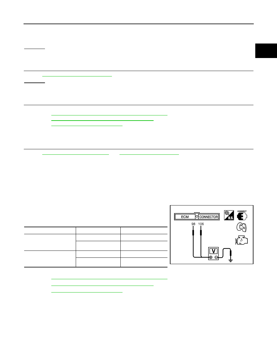
1. Reconnect all harness connectors disconnected.
2. Turn ignition switch ON.
3. Check voltage between ECM terminals 106 (APP sensor 1 sig-
nal), 98 (APP sensor 2 signal) and ground under the following
conditions.
4. If NG, replace accelerator pedal assembly and go to next step.
5. Perform
EC-18, "Accelerator Pedal Released Position Learning"
6. Perform
EC-18, "Throttle Valve Closed Position Learning"
.
7. Perform
EC-18, "Idle Air Volume Learning"
Continuity should exist.
Terminal
Accelerator pedal
Voltage
106
(Accelerator pedal position
sensor 1)
Fully released
0.5 - 1.0 V
Fully depressed
4.2 - 4.8 V
98
(Accelerator pedal position
sensor 2)
Fully released
0.25 - 0.5 V
Fully depressed
2.0 - 2.5 V
MBIB0023E
EC-370
< COMPONENT DIAGNOSIS >
[VK56DE]
P2127, P2128 APP SENSOR
P2127, P2128 APP SENSOR
Component Description
INFOID:0000000005149445
The accelerator pedal position sensor is installed on the upper end
of the accelerator pedal assembly. The sensor detects the accelera-
tor position and sends a signal to the ECM.
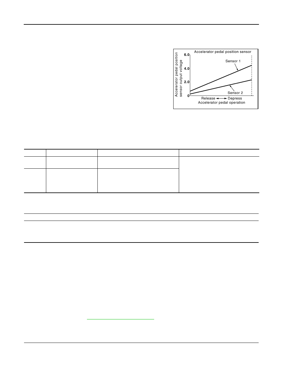
Accelerator pedal position sensor has two sensors. These sensors
are a kind of potentiometers which transform the accelerator pedal
position into output voltage, and emit the voltage signal to the ECM.
In addition, these sensors detect the opening and closing speed of
the accelerator pedal and feed the voltage signals to the ECM. The
ECM judges the current opening angle of the accelerator pedal from
these signals and controls the throttle control motor based on these
signals.
Idle position of the accelerator pedal is determined by the ECM
receiving the signal from the accelerator pedal position sensor. The ECM uses this signal for the engine oper-
ation such as fuel cut.
On Board Diagnosis Logic
INFOID:0000000005149446
These self-diagnoses have the one trip detection logic.
FAIL-SAFE MODE
When the malfunction is detected, ECM enters fail-safe mode and the MIL lights up.
DTC Confirmation Procedure
INFOID:0000000005149447
NOTE:
If DTC Confirmation Procedure has been previously conducted, always perform the following procedure
before conducting the next step.
1. Turn ignition switch OFF and wait at least 10 seconds.
2. Turn ignition switch ON.
3. Turn ignition switch OFF and wait at least 10 seconds.
TESTING CONDITION:
Before performing the following procedure, confirm that battery voltage is more than 8 V at idle.
1. Start engine and let it idle for 1 second.
2. Check DTC.
3. If DTC is detected, go to
.
Diagnosis Procedure
INFOID:0000000005149448
1.
CHECK GROUND CONNECTIONS
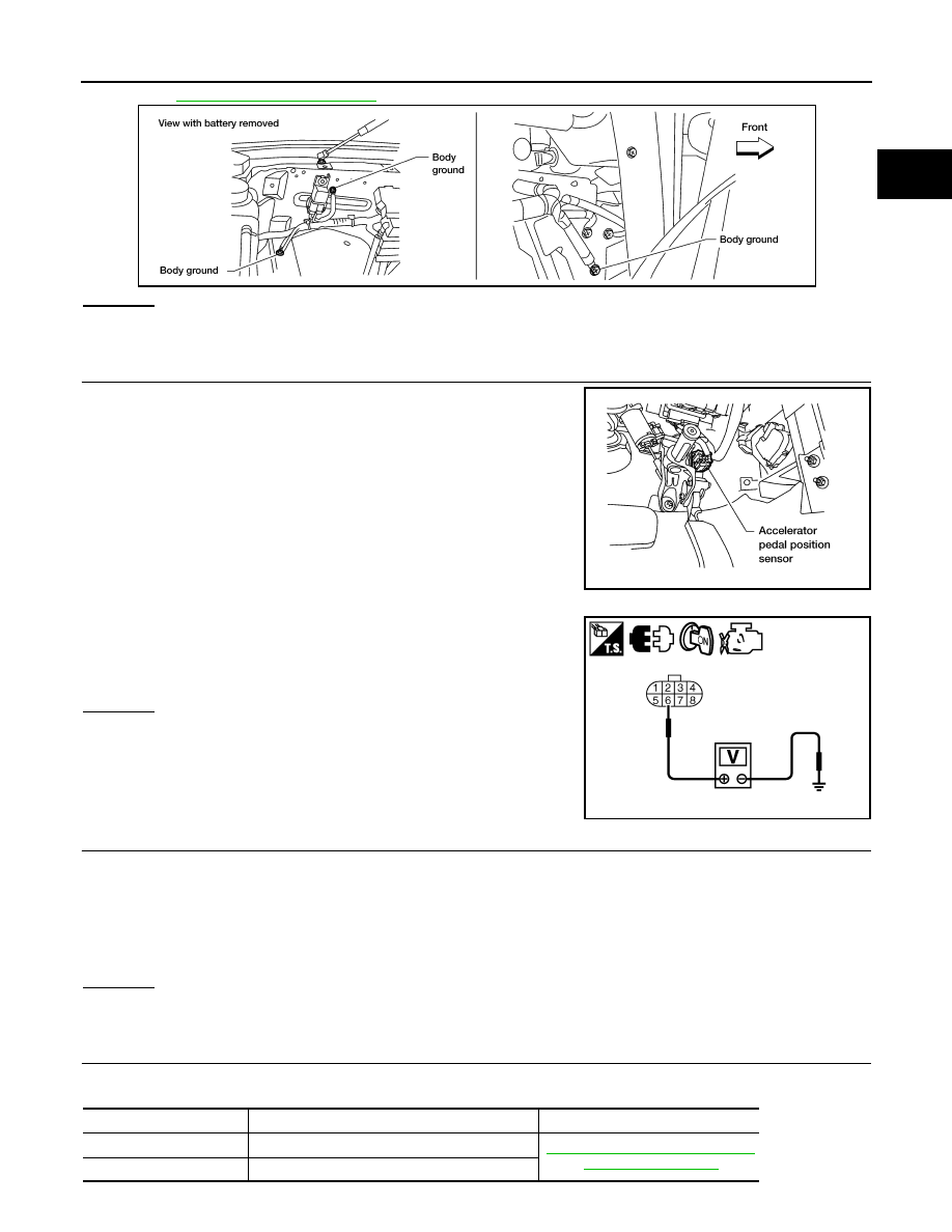
1. Turn ignition switch OFF.
2. Loosen and retighten three ground screws on the body.
PBIB1741E
DTC No.
Trouble diagnosis name
DTC detecting condition
Possible cause
P2127
2127
Accelerator pedal position
sensor 2 circuit low input
An excessively low voltage from the APP
sensor 2 is sent to ECM.
• Harness or connectors
(APP sensor 2 circuit is open or shorted.)
(TP sensor circuit is shorted.)
• Accelerator pedal position sensor
(Accelerator pedal position sensor 2)
• Electric throttle control actuator
(TP sensor)
P2128
2128
Accelerator pedal position
sensor 2 circuit high input
An excessively high voltage from the APP
sensor 2 is sent to ECM.
Engine operating condition in fail-safe mode
The ECM controls the electric throttle control actuator in regulating the throttle opening in order for the idle position to be within +10
degrees.
The ECM regulates the opening speed of the throttle valve to be slower than the normal condition.
So, the acceleration will be poor.
P2127, P2128 APP SENSOR
EC-371
< COMPONENT DIAGNOSIS >
[VK56DE]
C
D
E
F
G
H
I
J
K
L
M
A
EC
N
P
O
OK or NG
OK
>> GO TO 2.
NG
>> Repair or replace ground connections.
2.
CHECK APP SENSOR 2 POWER SUPPLY CIRCUIT-I
1. Disconnect accelerator pedal position (APP) sensor harness
connector.
2. Turn ignition switch ON.
3. Check voltage between APP sensor terminal 6 and ground with
CONSULT-III or tester.
OK or NG
OK
>> GO TO 7.
NG
>> GO TO 3.
3.
CHECK APP SENSOR 2 POWER SUPPLY CIRCUIT-II
1. Turn ignition switch OFF.
2. Disconnect ECM harness connector.
3. Check harness continuity between APP sensor terminal 6 and ECM terminal 91.
Refer to Wiring Diagram.
OK or NG
OK
>> GO TO 4.
NG
>> Repair open circuit.
4.
CHECK APP SENSOR 2 POWER SUPPLY CIRCUIT-III
Check harness for short to power and short to ground, between the following terminals
BBIA0354E
BBIA0361E
Voltage: Approximately 5 V
JMBIA0602ZZ
Continuity should exist.
ECM terminal
Sensor terminal
Reference Wiring Diagram
47
Electric throttle control actuator terminal 2
EC-435, "Wiring Diagram - ENGINE
91
APP sensor terminal 6
Нет комментариевНе стесняйтесь поделиться с нами вашим ценным мнением.
Текст