Infiniti QX56 (JA60). Manual — part 552
FSU-14
< REMOVAL AND INSTALLATION >
COIL SPRING AND SHOCK ABSORBER
REMOVAL AND INSTALLATION
COIL SPRING AND SHOCK ABSORBER
Removal and Installation
INFOID:0000000005148113
REMOVAL
1. Remove the wheel and tire using power tool.
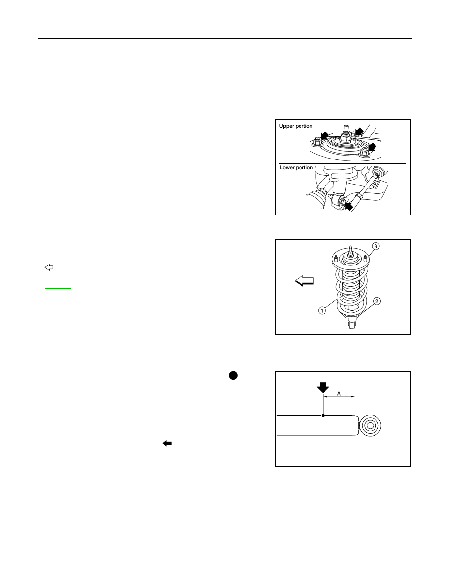
2. Remove the shock absorber lower bolt using power tool.
3. Remove the three shock absorber upper nuts using power tool.
4. Remove the coil spring and shock absorber assembly.
• Turn steering knuckle out to gain enough clearance for
removal.
INSTALLATION
Installation is in the reverse order of removal.
• The lower seat step (2) in the shock absorber assembly (1) faces
outside of vehicle.
- Upper spring insulator (3)
-
: Front
• Tighten all nuts and bolts to specification. Refer to
• When installing wheel and tire, refer to
Disposal
INFOID:0000000005369238
1. Set shock absorber horizontally with the piston rod fully extended.
2. Drill 2 – 3 mm (0.08 – 0.12 in) hole at the position ( ) from top
as shown in the figure to release gas gradually.
CAUTION:
• Wear eye protection (safety glasses).
• Wear gloves.
• Be careful with metal chips or oil blown out by the com-
pressed gas.
NOTE:
• Drill vertically in this direction (
).
• Directly to the outer tube avoiding brackets.
• The gas is clear, colorless, odorless, and harmless.
3. Position the drilled hole downward and drain oil by moving the piston rod several times.
CAUTION:
Dispose of drained oil according to the law and local regulations.
LEIA0093E
WEIA0155E
A
: 20 – 30 mm (0.79 – 1.18 in)
JPEIA0161ZZ
STABILIZER BAR
FSU-15
< REMOVAL AND INSTALLATION >
C
D
F
G
H
I
J
K
L
M
A
B
FSU
N
O
P
STABILIZER BAR
Removal and Installation
INFOID:0000000005148114
REMOVAL
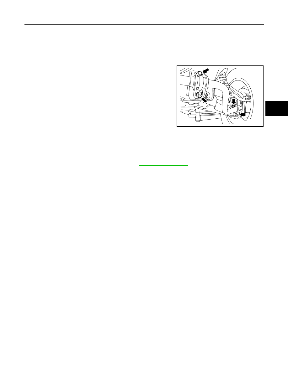
1. Remove engine under cover using power tool.
2. Remove stabilizer bar mounting bracket bolts and connecting
rod nuts using power tool, as shown.
3. Remove bushings from stabilizer bar.
INSPECTION AFTER REMOVAL
• Check stabilizer bar for twist and deformation. Replace if necessary.
• Check rubber bushing for cracks, wear and deterioration. Replace if necessary.
INSTALLATION
Installation is in the reverse order of removal.
• Tighten all nuts and bolts to specification. Refer to
LEIA0094E
FSU-16
< REMOVAL AND INSTALLATION >
UPPER LINK
UPPER LINK
Removal and Installation
INFOID:0000000005148115
REMOVAL
1. Remove the wheel and tire using power tool.
2. Remove the fender protector to access upper link. Refer to
EXT-23, "Removal and Installation"
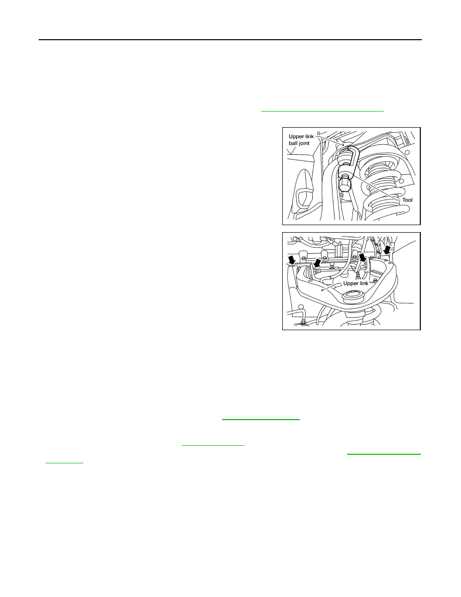
3. Remove cotter pin and nut from upper link ball joint and discard the cotter pin.
4. Separate upper link ball joint stud from steering knuckle using
Tool.
• Support lower link with jack.
5. Remove upper link bolts and nuts, then remove upper link.
INSPECTION AFTER REMOVAL
Upper Link
Check for deformation and cracks. Replace if necessary.
Upper Link Ball Joint
Check for distortion and damage. Replace if necessary.
INSTALLATION
Installation is in the reverse order of removal.
• Tighten all nuts and bolts to specification. Refer to
CAUTION:
Use a new cotter pin for installation of upper link ball joint nut.
• When installing wheel and tire, refer to
• After installation, check that the front wheel alignment is within specification. Refer to
.
Tool number
: ST29020001 (J-24319-01)
LEIA0095E
LEIA0096E
LOWER LINK
FSU-17
< REMOVAL AND INSTALLATION >
C
D
F
G
H
I
J
K
L
M
A
B
FSU
N
O
P
LOWER LINK
Removal and Installation
INFOID:0000000005148116
REMOVAL
1. Remove the wheel and tire using power tool.
2. Remove lower shock absorber bolt.
3. Remove stabilizer bar connecting rod lower nut using power tool, then separate connecting rod from lower
FSU-15, "Removal and Installation"
.
4. Remove drive shaft nut, if equipped. Refer to
FAX-9, "Removal and Installation"
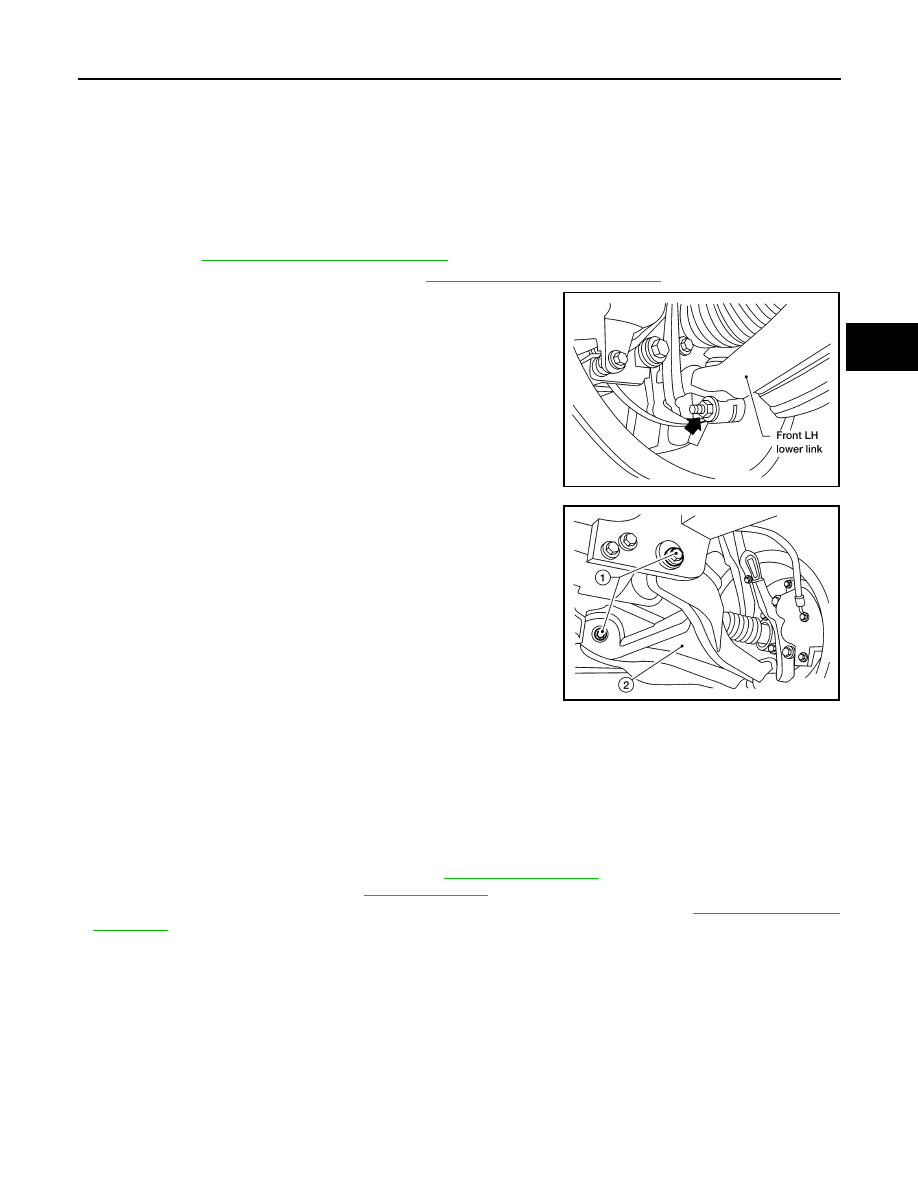
5. Remove pinch bolt from steering knuckle using power tool, then
separate lower link ball joint from steering knuckle.
6. Remove lower link bolts (1) and nuts, then the lower link (2).
INSPECTION AFTER REMOVAL
Lower Link
Check for deformation and cracks. Replace if necessary.
Lower Link Bushing
Check for distortion and damage. Replace if necessary.
INSTALLATION
Installation is in the reverse order of removal.
• Tighten all nuts and bolts to specification. Refer to
• When installing wheel and tire, refer to
.
• After installation, check that the front wheel alignment is within specification. Refer to
.
LEIA0097E
WEIA0153E
Нет комментариевНе стесняйтесь поделиться с нами вашим ценным мнением.
Текст