Infiniti G35 (V35) Sedan. Manual — part 616
TIMING CHAIN
EM-63
< ON-VEHICLE REPAIR >
C
D
E
F
G
H
I
J
K
L
M
A
EM
N
P
O
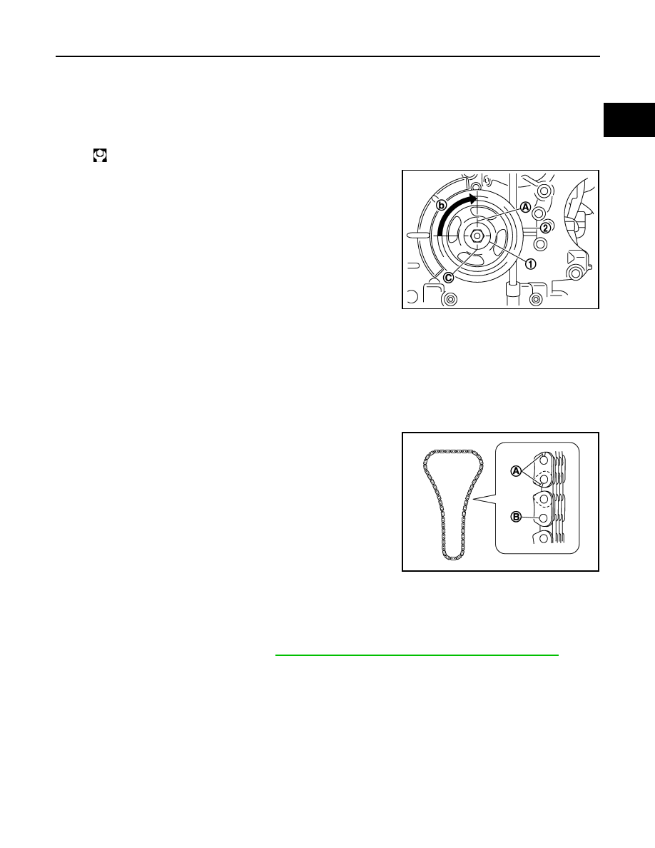
14. Install crankshaft pulley as follows:
a.
Fix crankshaft using the ring gear stopper [SST: KV10118600 (J-48641)].
b.
Install crankshaft pulley, taking care not to damage front oil seal.
• When press-fitting crankshaft pulley with plastic hammer, tap on its center portion (not circumference).
c.
Tighten crankshaft pulley bolt.
d.
Place a matching mark (A) on crankshaft pulley (2) aligning with
the matching (C) of crankshaft pulley bolt (1). Tighten the bolt 90
degrees (one marks) (b).
e.
Rotate crankshaft pulley in normal direction (clockwise when viewed from front) to confirm it turns
smoothly.
15. For the following operations, perform steps in the reverse order of removal.
Inspection
INFOID:0000000000956258
INSPECTION AFTER REMOVAL
Timing Chain
Check for cracks and any excessive wear at link plates and roller
links of timing chain. Replace timing chain as necessary.
INSPECTION AFTER INSTALLATION
Inspection for Leaks
The following are procedures for checking fluids leak, lubricates leak.
• Before starting engine, check oil/fluid levels including engine coolant and engine oil. If less than required
quantity, fill to the specified level. Refer to
GI-15, "Recommended Chemical Products and Sealants"
.
• Use procedure below to check for fuel leakage.
- Turn ignition switch “ON” (with engine stopped). With fuel pressure applied to fuel piping, check for fuel leak-
age at connection points.
- Start engine. With engine speed increased, check again for fuel leakage at connection points.
• Run engine to check for unusual noise and vibration.
NOTE:
If hydraulic pressure inside chain tensioner drops after removal/installation, slack in guide may generate a
pounding noise during and just after the engine start. However, this does not indicate an unusualness. Noise
will stop after hydraulic pressure rises.
• Warm up engine thoroughly to make sure there is no leakage of fuel, or any oil/fluids including engine oil and
engine coolant.
• Bleed air from lines and hoses of applicable lines, such as in cooling system.
: 44.1 N·m (4.5 kg-m, 33 ft-lb)
JPBIA0120ZZ
A
: Crack
B
: Wear
JPBIA0091ZZ

EM-64
< ON-VEHICLE REPAIR >
TIMING CHAIN
• After cooling down engine, again check oil/fluid levels including engine oil and engine coolant. Refill to the
specified level, if necessary.
Summary of the inspection items:
* Transmission/transaxle/CVT fluid, power steering fluid, brake fluid, etc.
Items
Before starting engine
Engine running
After engine stopped
Engine coolant
Level
Leakage
Level
Engine oil
Level
Leakage
Level
Other oils and fluid*
Level
Leakage
Level
Fuel
Leakage
Leakage
Leakage

CAMSHAFT
EM-65
< ON-VEHICLE REPAIR >
C
D
E
F
G
H
I
J
K
L
M
A
EM
N
P
O
CAMSHAFT
Exploded View
INFOID:0000000000956259
Removal and Installation
INFOID:0000000000956260
REMOVAL
1.
Camshaft bracket (No. 3, 4)
2.
Camshaft bracket (No. 2)
3.
Seal washer
4.
Camshaft bracket (No. 1)
5.
Dowel pin
6.
Camshaft (EXH) (right bank)
7.
Camshaft signal plate (EXH)
8.
Camshaft sensor bracket
9.
Dowel pin
10. Camshaft signal plate (INT)
11.
Camshaft (INT) (right bank)
12. Valve lifter
13. Cylinder head (right bank)
14.
Plunger
15. Spring
16.
Timing chain tensioner (secondary)
(right bank)
17.
Camshaft bracket (No. 3, 4)
18. Camshaft bracket (No. 2)
19. Camshaft bracket (No. 1)
20.
Camshaft signal plate (INT)
21. Camshaft signal plate (EXH)
22. Camshaft sensor bracket
23.
Cylinder head (left bank)
24.
Timing chain tensioner (secondary)
(left bank)
25. Camshaft (EXH)
26.
Camshaft (INT)
A.
Refer to
.
Refer to
for symbol marks in the figure.
JPBIA0067GB

EM-66
< ON-VEHICLE REPAIR >
CAMSHAFT
1.
Remove front timing chain case, camshaft sprocket and timing chain. Refer to
.
2.
Remove fuel sub tube. Refer to
.
3.
Loosen camshaft sensor bracket bolts in reverse order as
shown in the figure.
NOTE:
The order of loosening bolts is the same for bank 1 and bank 2.
4.
Remove camshaft brackets.
• Mark camshafts, camshaft brackets and bolts so they are placed in the same position and direction for
installation.
• Equally loosen camshaft bracket bolts in several steps in
reverse order as shown in the figure.
5.
Remove camshaft.
6.
Remove valve lifter.
• Identify installation positions, and store them without mixing them up.
7.
Remove timing chain tensioners (secondary) (1) from cylinder
head.
• Remove timing chain tensioners (secondary) with its stopper
pin (C) attached.
NOTE:
Stopper pin should be attached when timing chain (secondary)
is removed.
INSTALLATION
: Engine front
JPBIA0357ZZ
: Engine front
JPBIA0257ZZ
A
: Right bank
B
: Left bank
JPBIA0121ZZ
Нет комментариевНе стесняйтесь поделиться с нами вашим ценным мнением.
Текст