Infiniti G35 (V35) Sedan. Manual — part 1432

WCS-12
< FUNCTION DIAGNOSIS >
DIAGNOSIS SYSTEM (UNIFIED METER AND A/C AMP.)
DIAGNOSIS SYSTEM (UNIFIED METER AND A/C AMP.)
CONSULT-III Function (METER/M&A)
INFOID:0000000000964484
CONSULT-III APPLICATION ITEMS
CONSULT-III can perform the following diagnosis modes with CAN communication with the unified meter and
A/C amp.
SELF DIAG RESULT
.
DATA MONITOR
Display Item List
X: Applicable
System
Diagnosis mode
Description
METER/M&A
Self Diagnostic Result
Unified meter and A/C amp. checks the conditions and displays memorized error.
Data Monitor
Displays unified meter and A/C amp. input/output data in real time.
Display item [Unit]
MAIN
SIGNALS
Description
SPEED METER
[km/h]
X
Value of vehicle speed signal received from ABS actuator and electric unit (control
unit) with CAN communication line.
NOTE:
655.35 is displayed when the malfunction signal is received.
SPEED OUTPUT
[km/h]
X
Vehicle speed signal value transmitted to other units with CAN communication
line.
NOTE:
655.35 is displayed when the malfunction signal is received.
ODO OUTPUT
[km/h or mph]
Odometer signal value transmitted to other units with CAN communication line.
TACHO METER
[rpm]
X
Value of the engine speed signal received from ECM with CAN communication
line.
NOTE:
8191.875 is displayed when the malfunction signal is received.
FUEL METER
[lit.]
X
Fuel level indicated on combination meter.
W TEMP METER
[
°
C]
X
Value of engine coolant temperature signal received from ECM with CAN commu-
nication line.
NOTE:
215 is displayed when the malfunction signal is input.
ABS W/L
[On/Off]
Status of ABS warning lamp judged from ABS warning lamp signal received from
ABS actuator and electric unit (control unit) with CAN communication line.
VDC/TCS IND
[On/Off]
Status of VDC indicator lamp judged from VDC OFF indicator lamp signal re-
ceived from ABS actuator and electric unit (control unit) with CAN communication
line.
SLIP IND
[On/Off]
Status of slip indicator lamp judged from slip indicator lamp signal received from
ABS actuator and electric unit (control unit) with CAN communication line.
BRAKE W/L
[On/Off]
Status of brake warning lamp judged from brake warning lamp signal received
from ABS actuator and electric unit (control unit) with CAN communication line.
NOTE:
Displays “Off” if the brake warning lamp is illuminated when the valve check starts,
the parking brake switch is turned ON or the brake fluid level switch is turned ON.
DOOR W/L
[On/Off]
Status of door warning judged from door switch signal received from BCM with
CAN communication line.
TRUNK/GLAS-H
[On/Off]
Status of trunk warning judged from trunk switch signal received from BCM with
CAN communication line.

WCS
DIAGNOSIS SYSTEM (UNIFIED METER AND A/C AMP.)
WCS-13
< FUNCTION DIAGNOSIS >
C
D
E
F
G
H
I
J
K
L
M
B
N
A
O
P
HI-BEAM IND
[On/Off]
Status of high beam indicator lamp judged from high beam request signal received
from BCM with CAN communication line.
TURN IND
[On/Off]
Status of turn indicator lamp judged from turn indicator signal received from BCM
with CAN communication line.
FR FOG IND
[On/Off]
Status of front fog light indicator lamp judged from front fog light request signal re-
ceived from BCM with CAN communication line.
RR FOG IND
[Off]
This item is displayed, but cannot be monitored.
LIGHT IND
[On/Off]
Status of light indicator lamp judged from position light request signal received
from BCM with CAN communication line.
OIL W/L
[On/Off]
Status of oil pressure warning lamp judged from oil pressure switch signal re-
ceived from IPDM E/R with CAN communication line.
MIL
[On/Off]
Status of malfunction indicator lamp judged from malfunctioning indicator lamp
signal received from ECM with CAN communication line.
CRUISE IND
[On/Off]
Status of CRUISE indicator judged from ASCD status signal received from ECM
with CAN communication line.
SET IND
[On/Off]
Status of set indicator judged from ASCD SET indicator signal received from ECM
with CAN communication line.
CRUISE W/L
[On/Off]
Status of CRUISE warning lamp judged from ASCD status signal received from
ECM with CAN communication line.
BA W/L
[Off]
This item is displayed, but cannot be monitored.
ATC/T-AMT W/L
[On/Off]
Status of A/T check warning lamp judged from A/T check indicator signal received
from TCM with CAN communication line.
4WD W/L
[On/Off]
Status of AWD warning lamp judged from AWD warning lamp signal received from
AWD control unit with CAN communication line.
4WD LOCK IND
[Off]
This item is displayed, but cannot be monitored.
FUEL W/L
[On/Off]
Low-fuel warning status judged by the identified fuel level.
WASHER W/L
[On/Off]
Status of washer warning lamp judged from washer level switch input to combina-
tion meter.
AIR PRES W/L
[On/Off]
Status of tire pressure warning lamp judged from tire pressure signal received
from BCM with CAN communication line.
KEY G/Y W/L
[On/Off]
Status of key warning lamp (G/Y) judged from key warning signal received from
BCM with CAN communication line.
AFS OFF IND
[On/Off]
Status of AFS OFF indicator lamp judged from AFS OFF indicator lamp signal re-
ceived from AFS control unit with CAN communication line.
4WAS/RAS W/L
[On/Off]
Status of 4WAS warning lamp judged from 4WAS warning lamp signal received
from 4WAS main control unit with CAN communication line.
LCD
[B&P N, B&P I, ID NG, ROTAT, SFT
P, INSRT, BATT, NO KY,OUTKY, LK
WN, C&P N,C&P I]
Displays status of Intelligent Key system warning judged from meter display signal
received from BCM with CAN communication line.
ACC TARGET
[On/Off]
Status of vehicle ahead detection indicator judged from meter display signal re-
ceived from ICC sensor integrated unit with CAN communication line.
ACC DISTANCE
[Off, SHOR, MID, LONG]
Status of set distance indicator judged from meter display signal received from
ICC sensor integrated unit with CAN communication line.
ACC OWN VHL
[On/Off]
Status of own vehicle indicator judged from meter display signal received from
ICC sensor integrated unit with CAN communication line.
ACC SET SPEED
[On/Off]
Status of set vehicle speed indicator judged from meter display signal received
from ICC sensor integrated unit with CAN communication line.
Display item [Unit]
MAIN
SIGNALS
Description

WCS-14
< FUNCTION DIAGNOSIS >
DIAGNOSIS SYSTEM (UNIFIED METER AND A/C AMP.)
NOTE:
Some items are not available according to vehicle specification.
ACC UNIT
[On/Off]
Status of display unit judged from meter display signal received from ICC sensor
integrated unit with CAN communication line.
SHIFT IND
[P, R, N, D, M1, M2, M3, M4, M5]
Status of A/T position indicator judged from shift position signal and manual mode
indicator signal received from TCM with CAN communication line.
AT S MODE SW
[On/Off]
Status of snow mode switch.
AT P MODE SW
[On/Off]
This item is displayed, but cannot be monitored.
M RANGE SW
[On/Off]
Status of manual mode switch.
NM RANGE SW
[On/Off]
Status of not manual mode switch.
AT SFT UP SW
[On/Off]
Status of A/T shift up switch.
AT SFT DWN SW
[On/Off]
Status of A/T shift down switch.
ST SFT UP SW
[On/Off]
Status of paddle shifter up switch.
ST SFT DWN SW
[On/Off]
Status of paddle shifter down switch.
COMP FB SIG
[On/Off]
A/C compressor activation condition that ECM judges according to the water tem-
perature and the acceleration degree.
4WD LOCK SW
[Off]
This item is displayed, but cannot be monitored.
PKB SW
[On/Off]
Status of parking brake switch.
BUCKLE SW
[On/Off]
Status of seat belt buckle switch.
BRAKE OIL SW
[On/Off]
Status of brake fluid level switch.
DISTANCE
[km]
Value of possible driving distance calculated by unified meter and A/C amp.
OUTSIDE TEMP
[
°
C or
°
F]
Ambient temperature value converted from ambient sensor signal received from
ambient sensor.
NOTE:
This may not match with the temperature value indicated on the information dis-
play. (Because the information display value is a corrected value from the ambient
sensor input value.)
FUEL LOW SIG
[On/Off]
Status of fuel level low warning signal to output to AV control unit with CAN com-
munication line.
BUZZER
[On/Off]
Buzzer status (in the combination meter) is judged with the buzzer output signal
received from each unit with CAN communication line and the warning output con-
dition of the combination meter.
Display item [Unit]
MAIN
SIGNALS
Description
WCS
DIAGNOSIS SYSTEM (BCM)
WCS-15
< FUNCTION DIAGNOSIS >
C
D
E
F
G
H
I
J
K
L
M
B
N
A
O
P
DIAGNOSIS SYSTEM (BCM)
COMMON ITEM
COMMON ITEM : CONSULT-III Function (BCM - COMMON ITEM)
INFOID:0000000000964485
APPLICATION ITEM
CONSULT-III performs the following functions via CAN communication with BCM.
SYSTEM APPLICATION
BCM can perform the following functions for each system.
NOTE:
It can perform the diagnosis modes except the following for all sub system selection items.
*: This item is displayed, but is not used.
BUZZER
BUZZER : CONSULT-III Function (BCM - BUZZER)
INFOID:0000000000964486
CONSULT-III APPLICATION ITEMS
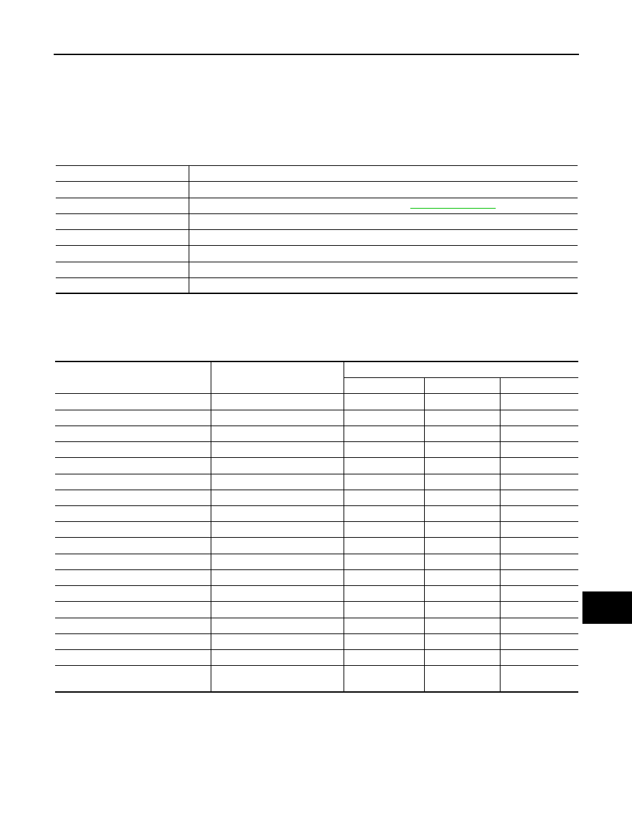
Diagnosis mode
Function Description
WORK SUPPORT
Changes the setting for each system function.
SELF-DIAG RESULTS
Displays the diagnosis results judged by BCM. Refer to
CAN DIAG SUPPORT MNTR
Monitors the reception status of CAN communication viewed from BCM.
DATA MONITOR
The BCM input/output signals are displayed.
ACTIVE TEST
The signals used to activate each device are forcibly supplied from BCM.
ECU IDENTIFICATION
The BCM part number is displayed.
CONFIGURATION
This function is not used even though it is displayed.
System
Sub system selection item
Diagnosis mode
WORK SUPPORT
DATA MONITOR
ACTIVE TEST
Door lock
DOOR LOCK
×
×
×
Rear window defogger
REAR DEFOGGER
×
×
Warning chime
BUZZER
×
×
Interior room lamp timer
INT LAMP
×
×
×
Exterior lamp
HEAD LAMP
×
×
×
Wiper and washer
WIPER
×
×
×
Turn signal and hazard warning lamps
FLASHER
×
×
×
Air conditioner*
AIR CONDITONER
×
Intelligent Key system
INTELLIGENT KEY
×
×
×
Combination switch
COMB SW
×
BCM
BCM
×
IVIS - NATS
IMMU
×
×
Interior room lamp battery saver
BATTERY SAVER
×
×
×
Trunk open
TRUNK
×
Vehicle security system
THEFT ALM
×
×
×
RAP system
RETAINED PWR
×
Signal buffer system
SIGNAL BUFFER
×
×
TPMS
TPMS (AIR PRESSURE MONI-
TOR)
×
×
×
Нет комментариевНе стесняйтесь поделиться с нами вашим ценным мнением.
Текст