Infiniti G35 (V35) Sedan. Manual — part 198
BCS
SIGNAL BUFFER SYSTEM
BCS-9
< FUNCTION DIAGNOSIS >
C
D
E
F
G
H
I
J
K
L
B
A
O
P
N
SIGNAL BUFFER SYSTEM
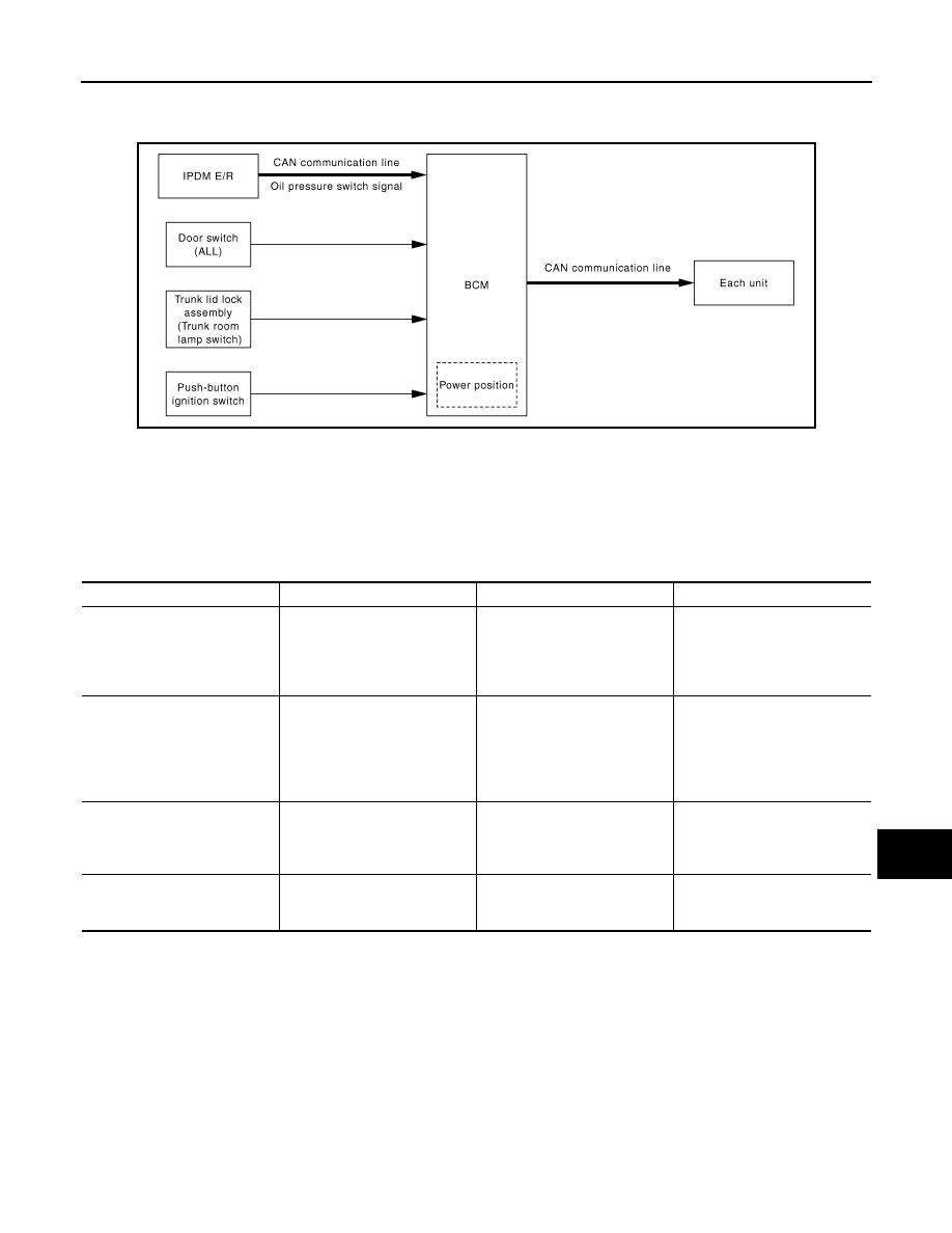
System Diagram
INFOID:0000000000963866
System Description
INFOID:0000000000963867
OUTLINE
BCM has the signal transmission function that outputs/transmits each input/received signal to each unit.
Signal transmission function list
JPMIA0070GB
Signal name
Input
Output
Description
• Ignition switch ON signal
• Ignition switch signal
Push-button ignition switch
(push switch)
• IPDM E/R (CAN)
• Driver seat control unit (CAN)
Inputs the push-button ignition
switch (push switch) signal and
transmits the ignition switch sta-
tus judged with BCM via CAN
communication.
Door switch signal
Any door switch
• Combination meter (via uni-
fied meter and A/C amp.)
(CAN)
• IPDM E/R (CAN)
• Driver seat control unit (CAN)
• AV control unit (CAN)
Inputs the door switch signal
and transmits it via CAN com-
munication.
Trunk switch signal
Trunk room lamp switch
• Combination meter (via uni-
fied meter and A/C amp.)
(CAN)
• AV control unit (CAN)
Inputs the trunk room lamp
switch signal and transmits the
trunk switch signal via CAN
communication.
Oil pressure switch signal
IPDM E/R (CAN)
Combination meter (via unified
meter and A/C amp.) (CAN)
Transmits the received oil pres-
sure switch signal via CAN
communication.
BCS-10
< FUNCTION DIAGNOSIS >
POWER CONSUMPTION CONTROL SYSTEM
POWER CONSUMPTION CONTROL SYSTEM
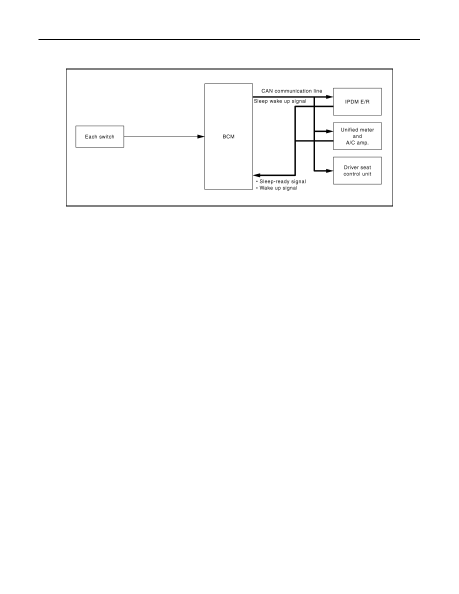
System Diagram
INFOID:0000000000963868
System Description
INFOID:0000000000963869
OUTLINE
• BCM incorporates a power saving control function that reduces the power consumption according to the
vehicle status.
• BCM switches the status (control mode) by itself with the power saving control function. It performs the sleep
request to each unit [IPDM E/R, combination meter (unified meter and A/C amp.) and driver seat control unit]
that operates with the ignition switch OFF.
Normal mode (wake-up)
- CAN communication is normally performed with other units
- Each control with BCM is operating properly
CAN communication sleep mode (CAN sleep)
- CAN transmission is stopped
- Control with BCM only is operating
Low power consumption mode (BCM sleep)
- Low power consumption control is active
- CAN transmission is stopped
LOW POWER CONSUMPTION CONTROL WITH BCM
BCM reduces the power consumption with the following operation in the low power consumption mode.
• The reading interval of the each switches changes from 10 ms interval to 60 ms interval.
Sleep mode activation
• BCM receives the sleep-ready signal (ready) from IPDM E/R and unified meter and A/C amp. via CAN com-
munication.
• BCM transmits the sleep wake up signal (sleep) to each unit when all of the CAN sleep conditions are ful-
filled.
• Each unit stops the transmission of CAN communication with the sleep wake up signal. BCM is in CAN com-
munication sleep mode.
• BCM is in the low power consumption mode and perform the low power consumption control when all of the
BCM sleep conditions are fulfilled with CAN sleep condition.
JPMIA0069GB

BCS
POWER CONSUMPTION CONTROL SYSTEM
BCS-11
< FUNCTION DIAGNOSIS >
C
D
E
F
G
H
I
J
K
L
B
A
O
P
N
Sleep condition
Wake-up operation
• BCM changes from the low power consumption mode to the CAN communication sleep mode when the any
of the BCM wake-up conditions is fulfilled. Only the control with BCM is activated.
• BCM transmits the sleep wake up signal (wake up) to each unit when any of the CAN wake-up conditions is
fulfilled. It changes from the low power consumption mode or the CAN communication sleep mode to the
normal mode.
• Each unit starts the transmission of CAN communication with the sleep wake up signal. In addition, the uni-
fied meter and A/C amp. transmits the wake up signal to BCM via CAN communication to report the CAN
communication start.
Wake-up condition
Component Parts Location
INFOID:0000000000963870
CAN sleep condition
BCM sleep condition
• Receiving the sleep-ready signal (ready) from all units
• Ignition switch: OFF
• Vehicle security system and panic alarm: Not operation
• Warning lamp: Not operation
• Intelligent Key system buzzer: Not operation
• Trunk room lamp switch status: No change
• Brake switch: OFF
• Key slot (card switch) status: No change
• Turn signal indicator lamp: Not operation
• Exterior lamp: OFF
• Door lock status: No change
• CONSULT-III communication status: Not communication
• Meter display signal: Non-transmission
• Steering lock operation: Not operation
• Door switch status: No change
• Rear window defogger: OFF
• Interior room lamp battery saver: Time out
• RAP system: OFF
• Power window switch communication: No transmission
• Push-button ignition switch illumination: OFF
• Infiniti Vehicle Immobilizer System (IVIS) - NATS: Not opera-
tion
• Remote keyless entry receiver communication status: No com-
munication
• Tire pressure monitor system (TPMS) - AIR PRESSURE
MONITOR: Stop
BCM wake-up condition
CAN wake-up condition
• Trunk lid opener switch: OFF
→
ON
• Power window switch communication: Receiving
• Remote keyless entry receiver: Receiving
• Receiving the sleep-ready signal (Not-ready) from any units
• Key slot (key switch): OFF
→
ON, ON
→
OFF
• Push-button ignition switch (push switch): OFF
→
ON
• Hazard switch: OFF
→
ON
• PASSING switch: OFF
→
ON, ON
→
OFF
• TAIL LAMP switch: OFF
→
ON
• Driver door switch: OFF
→
ON, ON
→
OFF
• Passenger door switch: OFF
→
ON, ON
→
OFF
• Rear RH door switch: OFF
→
ON, ON
→
OFF
• Rear LH door switch: OFF
→
ON, ON
→
OFF
• Trunk room lamp switch: OFF
→
ON, ON
→
OFF
• Driver door request switch: OFF
→
ON
• Passenger door request switch: OFF
→
ON
• Trunk request switch: OFF
→
ON
• Stop lamp switch 2 signal: ON
• Clutch interlock switch: OFF
→
ON

BCS-12
< FUNCTION DIAGNOSIS >
POWER CONSUMPTION CONTROL SYSTEM
1.
BCM
2.
IPDM E/R
3.
Unified meter and A/C amp.
4.
Driver seat control unit
A.
Dash side lower (passenger side)
B.
Engine room dash panel (RH)
C.
Behind Cluster lid C
D.
Backside of the seat cushion (driver
seat)
JPMIA0072ZZ
Нет комментариевНе стесняйтесь поделиться с нами вашим ценным мнением.
Текст