Infiniti G35 (V35) Sedan. Manual — part 783

HAC-104
< COMPONENT DIAGNOSIS >
[AUTOMATIC AIR CONDITIONER]
INTAKE SENSOR
After disconnecting intake sensor (1) connector M77, measure resis-
tance between terminals 1 and 2 at sensor side. Refer to table
below.
If NG, replace intake sensor.
Temperature
°
C (
°
F)
Resistance k
Ω
−
15 (5)
12.34
−
10 (14)
9.62
−
5 (23)
7.56
0 (32)
6.00
5 (41)
4.80
10 (50)
3.87
15 (59)
3.15
20 (68)
2.57
25 (77)
2.12
30 (86)
1.76
35 (95)
1.47
40 (104)
1.23
45 (113)
1.04
JSIIA0053ZZ
POWER SUPPLY AND GROUND CIRCUIT FOR AUTO AMP.
HAC-105
< COMPONENT DIAGNOSIS >
[AUTOMATIC AIR CONDITIONER]
C
D
E
F
G
H
J
K
L
M
A
B
HAC
N
O
P
POWER SUPPLY AND GROUND CIRCUIT FOR AUTO AMP.
Description
INFOID:0000000000959968
COMPONENT DESCRIPTION
Unified Meter and A/C Amp. (Automatic Amplifier)
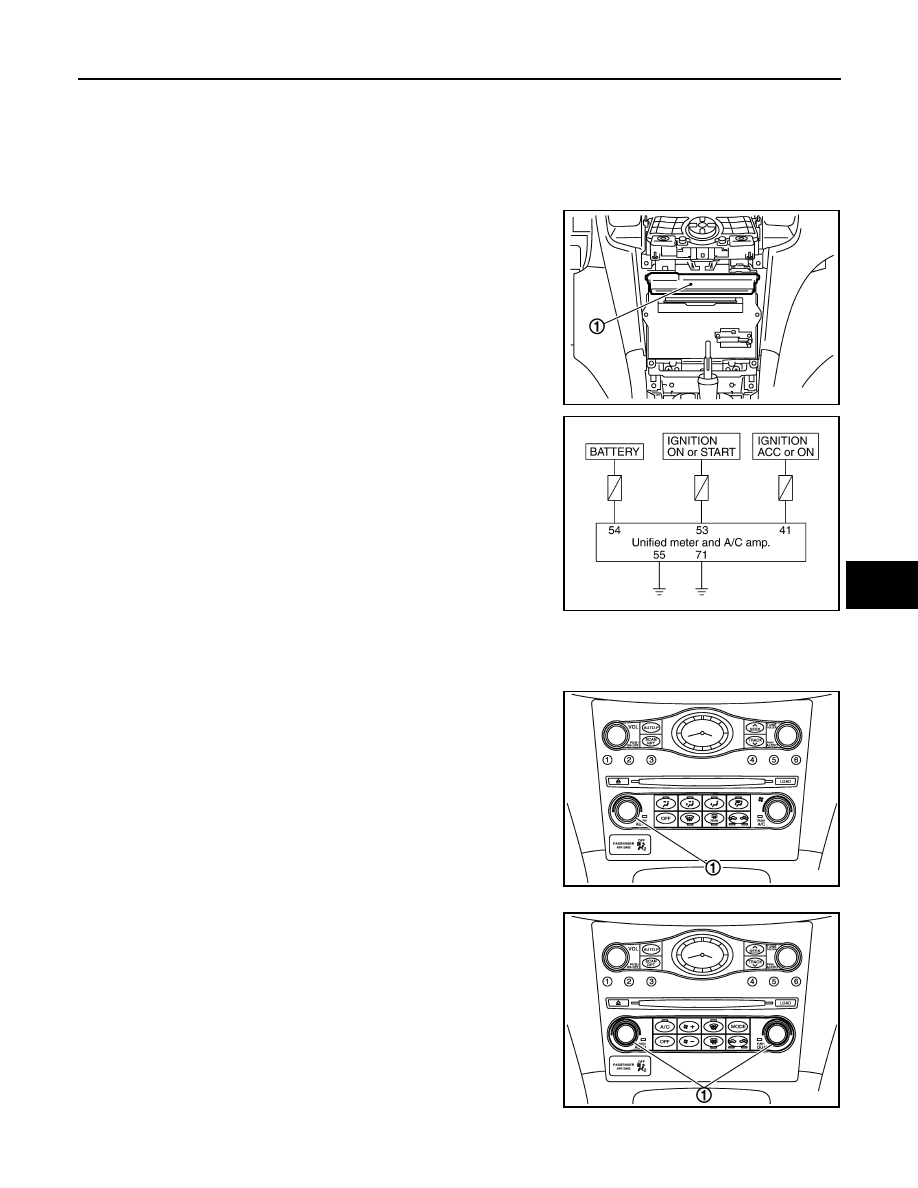
The unified meter and A/C amp. (1) has a built-in microcomputer
which processes information sent from various sensors needed for
air conditioner operation. The air mix door motor(s), mode door
motor, intake door motor, blower motor and compressor are then
controlled.
When the various switches and temperature control dial are oper-
ated, data is input to the unified meter and A/C amp. from the AV
control unit using CAN communication.
Self-diagnosis functions are also built into unified meter and A/C
amp. to provide quick check of malfunctions in the auto air condi-
tioner system.
Power Supply and Ground Circuit for Unified Meter and A/C Amp.
Potentio Temperature Control (PTC)
The PTC (1) is built into the preset switch. It can be set at an interval of 0.5
°
C (1.0
°
F) in the 18
°
C (60
°
F) to
32
°
C (90
°
F) temperature range by turning temperature control dial. The set temperature is displayed.
Without left and right ventilation temperature separately system
With left and right ventilation temperature separately system
Component Function Check
INFOID:0000000000959969
JSIIA0014GB
RJIA4049E
JSIIA0135ZZ
JSIIA0020GB

HAC-106
< COMPONENT DIAGNOSIS >
[AUTOMATIC AIR CONDITIONER]
POWER SUPPLY AND GROUND CIRCUIT FOR AUTO AMP.
1.
CONFIRM SYMPTOM BY PERFORMING THE FOLLOWING OPERATIONAL CHECK
1.
Press AUTO switch and A/C switch.
2.
Display should indicate AUTO. Confirm that the compressor clutch engages (sound or visual inspection).
(Discharge air and blower speed will depend on ambient, in-vehicle and set temperatures.)
Does magnet clutch engaged?
YES
>> END.
NO
>> Go to Diagnosis Procedure. Refer to
HAC-106, "Diagnosis Procedure"
Diagnosis Procedure
INFOID:0000000000959970
1.
CHECK POWER SUPPLY CIRCUIT FOR UNIFIED METER AND A/C AMP.
1.
Disconnect unified meter and A/C amp. connector.
2.
Check voltage between unified meter and A/C amp. harness connector M67 terminals 41, 53 and 54 and
ground.
Is the inspection result normal?
YES
>> GO TO 3.
NO
>> GO TO 2.
2.
CHECK FUSE
Check 10A fuses [Nos. 3, 6 and 19, located in the fuse block (J/B)]. Refer to
PG-93, "Fuse, Connector and Ter-
.
Is the inspection result normal?
YES
>> Check harness for open circuit. Repair or replace if necessary.
NO
>> Check harness for short circuit and replace fuse.
3.
CHECK GROUND CIRCUIT FOR UNIFIED METER AND A/C AMP.
1.
Turn ignition switch OFF.
2.
Check continuity between unified meter and A/C amp. harness connector M67 terminal 55, 71 and
ground.
Is the inspection result normal?
YES
>> GO TO 4.
NO
>> Repair harness or connector.
4.
CHECK PRESET SWITCH
Check preset switch. Refer to
(BASE AUDIO WITHOUT NAVIGATION),
(BOSE AUDIO WITHOUT NAVIGATION) or
(BOSE AUDIO WITH
NAVIGATION).
Is the inspection result normal?
YES
>> Replace unified meter and A/C amp.
NO
>> Repair or replace malfunctioning part(s).
(+)
(-)
Ignition switch position
Unified meter and A/C amp.
—
OFF
ACC
ON
Connector
Terminal
M67
41
Ground
Approx. 0 V
Battery voltage
Battery voltage
53
Approx. 0 V
Approx. 0 V
Battery voltage
54
Battery voltage
Battery voltage
Battery voltage
(+)
(
−
)
Continuity
Unified meter and A/C amp.
—
Connector
Terminal
M67
55
Ground
Continuity should exist
71

AUTO AMP.
HAC-107
< ECU DIAGNOSIS >
[AUTOMATIC AIR CONDITIONER]
C
D
E
F
G
H
J
K
L
M
A
B
HAC
N
O
P
ECU DIAGNOSIS
AUTO AMP.
Reference Value
INFOID:0000000000959971
VALUES ON THE DIAGNOSIS TOOL
Display Item List
TERMINAL LAYOUT
PHYSICAL VALUES
Monitor Item
Condition
Value/Status
IGN ON SW
Ignition switch OFF
→
ON
OFF
→
ON
FAN ON SIG
Ignition switch ON
Blower fan motor switch ON
ON
Blower fan motor switch OFF
OFF
AIR COND SW
Ignition switch ON
Compressor ON
ON
Compressor OFF
OFF
REFRIGERANT PRESSURE
SENSOR
• Engine is running
• Warm-up condition
• Both A/C switch and blower fan motor switch: ON (Compressor
operates)
1.0 - 4.0 V
JSIIA0097ZZ
Terminal No.
(Wire color)
Description
Condition
Value
(Approx.)
+
−
Signal name
Input/
Output
38
(L)
Ground
Blower motor control signal
Output
• Ignition switch ON
• Blower speed: 1st speed
(manual)
41
(V)
Ground
Power supply from ACC
—
Ignition switch ACC
Battery voltage
43
(R)
Ground
Intake sensor
Input
—
—
44
(LG)
Ground
In-vehicle sensor
Input
—
—
45
(P)
Ground
Ambient sensor
Input
—
—
46
(O)
Ground
Sunload sensor
Input
—
—
JSIIA0096ZZ
Нет комментариевНе стесняйтесь поделиться с нами вашим ценным мнением.
Текст