Infiniti I30. Emission Control System (2003 year). Manual — part 14

DTC Confirmation Procedure
NHEC1456
NOTE:
If “DTC Confirmation Procedure” has been previously conducted,
always turn ignition switch “OFF” and wait at least 10 seconds
before conducting the next test.
TESTING CONDITION:
Before performing the following procedure, confirm that bat-
tery voltage is more than 10V at idle.
SEF058Y
With CONSULT-II
1)
Turn ignition switch “ON”.
2)
Select “DATA MONITOR” mode with CONSULT-II.
3)
Start engine and let it idle for 1 second.
4)
If DTC is detected, go to “Diagnostic Procedure”, EC-211.
With GST
Follow the procedure “With CONSULT-II” above.
GI
MA
EM
LC
FE
AT
AX
SU
BR
ST
RS
BT
HA
SC
EL
IDX
DTC P0122, P0123 TP SENSOR
DTC Confirmation Procedure
EC-209

Wiring Diagram
NHEC1337
MEC362E
DTC P0122, P0123 TP SENSOR
Wiring Diagram
EC-210

Specification data are reference values and are measured between each terminal and ground.
CAUTION:
Do not use ECM ground terminals when measuring input/output voltage. Doing so may result in dam-
age to the ECM’s transistor. Use a ground other than ECM terminals, such as the ground.
TERMI-
NAL
NO.
WIRE
COLOR
ITEM
CONDITION
DATA (DC Voltage)
58
B
Sensors’ ground
[Engine is running]
쐌
Warm-up condition
쐌
Idle speed
Approximately 0V
83
W
Throttle position sensor
1
[Ignition switch “ON”]
쐌
Engine stopped
쐌
Shift lever position is “D”
쐌
Accelerator pedal released
More than 0.36V
[Ignition switch “ON”]
쐌
Engine stopped
쐌
Shift lever position is “D”
쐌
Accelerator pedal fully depressed
Less than 4.75V
84
L
Throttle position sensor
2
[Ignition switch “ON”]
쐌
Engine stopped
쐌
Shift lever position is “D”
쐌
Accelerator pedal released
Less than 4.75V
[Ignition switch “ON”]
쐌
Engine stopped
쐌
Shift lever position is “D”
쐌
Accelerator pedal fully depressed
More than 0.36V
111
R
Sensor’s power supply
[Ignition switch “ON”]
Approximately 5V
Diagnostic Procedure
NHEC1338
1
RETIGHTEN GROUND SCREWS
1. Turn ignition switch “OFF”.
2. Loosen and retighten engine ground screws.
SEC047D
䊳
GO TO 2.
GI
MA
EM
LC
FE
AT
AX
SU
BR
ST
RS
BT
HA
SC
EL
IDX
DTC P0122, P0123 TP SENSOR
Wiring Diagram (Cont’d)
EC-211
2
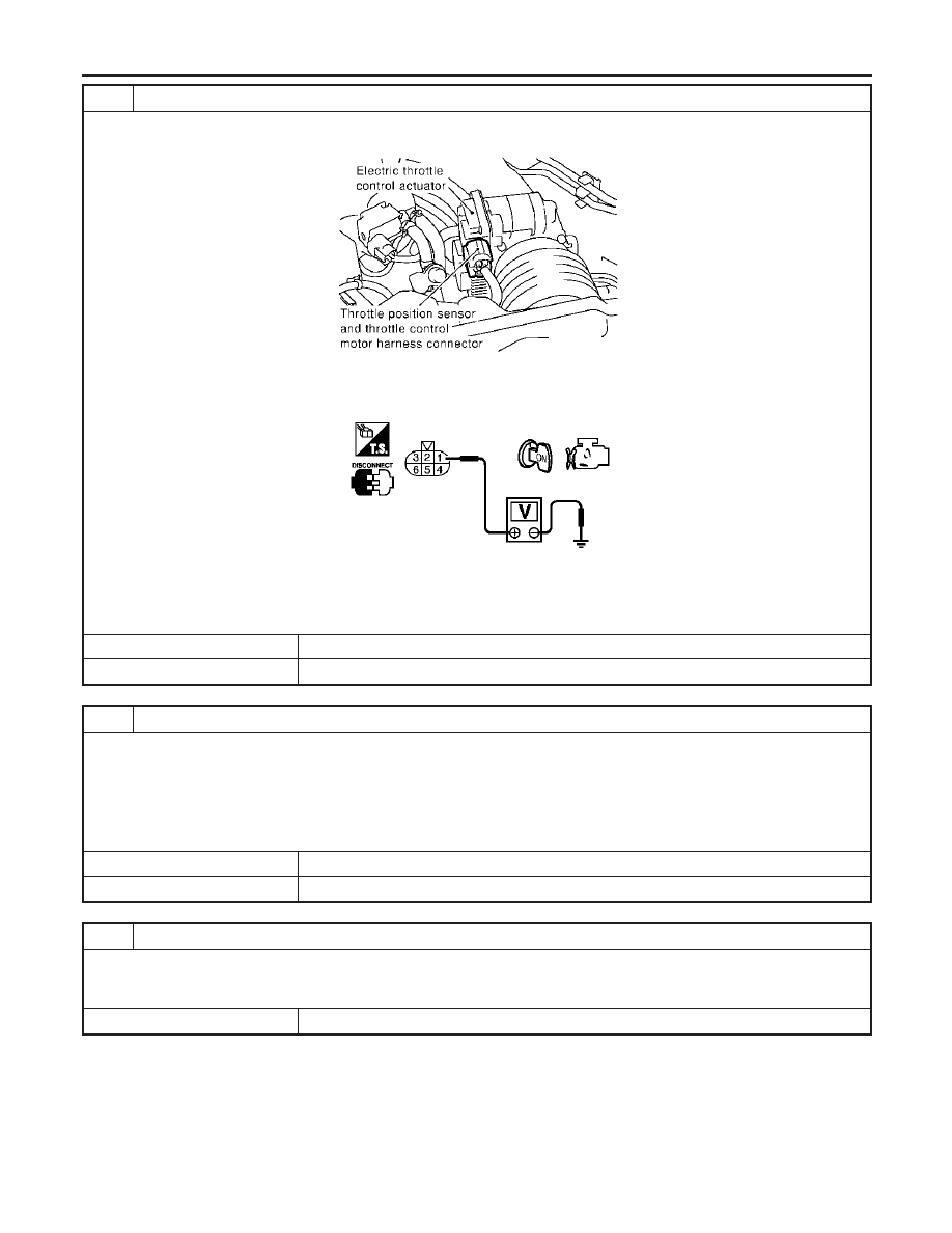
CHECK THROTTLE POSITION SENSOR 2 POWER SUPPLY CIRCUIT
1. Disconnect electric throttle control actuator harness connector.
2. Turn ignition switch “ON”.
SEC054D
3. Check voltage between electric throttle control actuator terminal 1 and ground with CONSULT-II or tester.
PBIB0082E
Voltage: Approximately 5V
OK or NG
OK
䊳
GO TO 3.
NG
䊳
Repair open circuit or short to ground or short to power in harness or connectors.
3
CHECK THROTTLE POSITION SENSOR 2 GROUND CIRCUIT FOR OPEN AND SHORT
1. Turn ignition switch “OFF”.
2. Check harness continuity between electric throttle control actuator terminal 5 and engine ground.
Refer to Wiring Diagram.
Continuity should exist.
3. Also check harness for short to ground and short to power.
OK or NG
OK
䊳
GO TO 5.
NG
䊳
GO TO 4.
4
DETECT MALFUNCTIONING PART
Check the following.
쐌
Joint connector-20
쐌
Harness for open or short between electric throttle control actuator and ECM
䊳
Repair open circuit or short to ground or short to power in harness or connectors.
DTC P0122, P0123 TP SENSOR
Diagnostic Procedure (Cont’d)
EC-212
5
CHECK THROTTLE POSITION SENSOR 2 INPUT SIGNAL CIRCUIT FOR OPEN AND SHORT
1. Disconnect ECM harness connector.
2. Check harness continuity between ECM terminal 84 and electric throttle control actuator terminal 2.
Refer to Wiring Diagram.
Continuity should exist.
3. Also check harness for short to ground and short to power.
OK or NG
OK
䊳
GO TO 6.
NG
䊳
Repair open circuit or short to ground or short to power in harness or connectors.
6
CHECK THROTTLE POSITION SENSOR
Refer to “Component Inspection”, EC-213.
OK or NG
OK
䊳
GO TO 8.
NG
䊳
GO TO 7.
7
REPLACE ELECTRIC THROTTLE CONTROL ACTUATOR
1. Replace the electric throttle control actuator.
2. Perform “Throttle Valve Closed Position Learning”, EC-71.
3. Perform “Idle Air Volume Learning”, EC-71.
䊳
INSPECTION END
8
CHECK INTERMITTENT INCIDENT
Refer to “TROUBLE DIAGNOSIS FOR INTERMITTENT INCIDENT”, EC-151.
䊳
INSPECTION END
SEC900C
Component Inspection
NHEC1339
THROTTLE POSITION SENSOR
1.
Reconnect all harness connectors disconnected.
2.
Perform “Throttle Valve Closed Position Learning”, EC-71.
3.
Turn ignition switch “ON”.
4.
Set selector lever to “D” position.
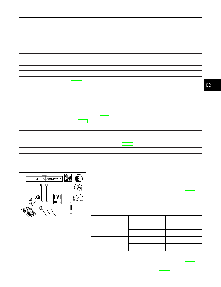
5.
Check voltage between ECM terminals 83 (TP sensor 1), 84
(TP sensor 2) and engine ground under the following condi-
tions.
Terminal
Accelerator pedal
Voltage
83
(Throttle position sensor
1)
Fully released
More than 0.36V
Fully depressed
Less than 4.75V
84
(Throttle position sensor
2)
Fully released
Less than 4.75V
Fully depressed
More than 0.36V
6.
If NG, replace electric throttle control actuator and go to the
next step.
7.
Perform “Throttle Valve Closed Position Learning”, EC-71.
8.
Perform “Idle Air Volume Learning”, EC-71.
GI
MA
EM
LC
FE
AT
AX
SU
BR
ST
RS
BT
HA
SC
EL
IDX
DTC P0122, P0123 TP SENSOR
Diagnostic Procedure (Cont’d)
EC-213

Description
NHEC0869
NOTE:
If DTC P0125 is displayed with P0117, P0118, first perform the
trouble diagnosis for DTC P0117, P0118. Refer to EC-203.
SEF594K
COMPONENT DESCRIPTION
NHEC0869S01
The engine coolant temperature sensor is used to detect the
engine coolant temperature. The sensor modifies a voltage signal
from the ECM. The modified signal returns to the ECM as the
engine coolant temperature input. The sensor uses a thermistor
which is sensitive to the change in temperature. The electrical
resistance of the thermistor decreases as temperature increases.
SEF012P
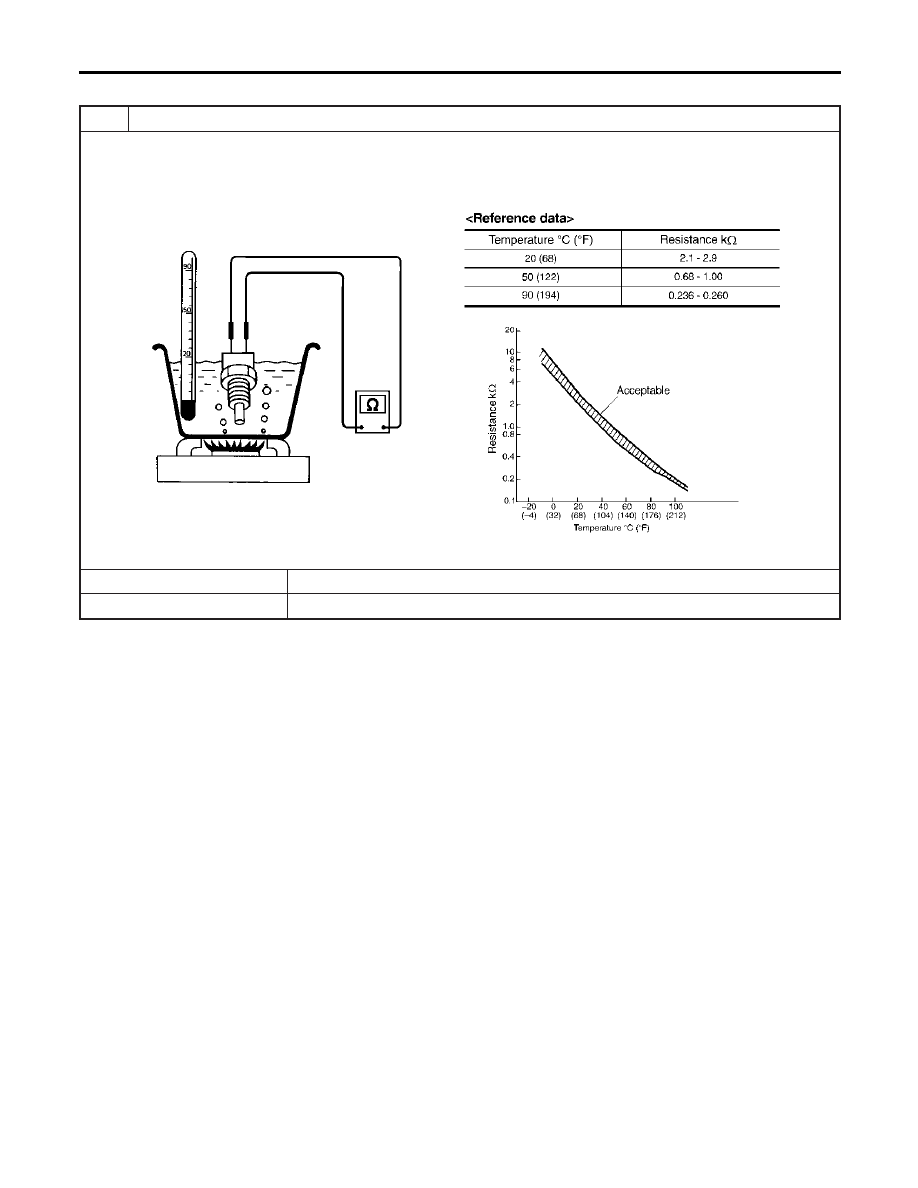
<Reference data>
Engine coolant
temperature
°C (°F)
Voltage*
V
Resistance
k
Ω
−10 (14)
4.4
7.0 - 11.4
20 (68)
3.5
2.1 - 2.9
50 (122)
2.2
0.68 - 1.00
90 (194)
0.9
0.236 - 0.260
*: These data are reference values and are measured between ECM terminal 93
(Engine coolant temperature sensor) and ground.
CAUTION:
Do not use ECM ground terminals when measuring input/
output voltage. Doing so may result in damage to the ECM’s
transistor. Use a ground other than ECM terminals, such as
the ground.
On Board Diagnosis Logic
NHEC0870
This self-diagnosis has the one trip detection logic.
DTC No.
Trouble diagnosis
name
DTC Detecting Condition
Possible Cause
P0125
0125
Insufficient engine
coolant temperature
for closed loop fuel
control
쐌
Voltage sent to ECM from the sensor is not
practical, even when some time has passed
after starting the engine.
쐌
Engine coolant temperature is insufficient for
closed loop fuel control.
쐌
Harness or connectors
(The sensor circuit is open or
shorted.)
쐌
Engine coolant temperature sensor
쐌
Thermostat
DTC P0125 ECT SENSOR
Description
EC-214

SEF174Y
DTC Confirmation Procedure
NHEC0871
CAUTION:
Be careful not to overheat engine.
NOTE:
If “DTC Confirmation Procedure” has been previously conducted,
always turn ignition switch “OFF” and wait at least 10 seconds
before conducting the next test.
WITH CONSULT-II
NHEC0871S01
1)
Turn ignition switch “ON”.
2)
Select “DATA MONITOR” mode with CONSULT-II.
3)
Check that “COOLAN TEMP/S” is above 10°C (50°F).
If it is above 10°C (50°F), the test result will be OK.
If it is below 10°C (50°F), go to following step.
4)
Start engine and run it for 65 minutes at idle speed.
If “COOLAN TEMP/S” increases to more than 10°C (50°F)
within 65 minutes, stop engine because the test result will
be OK.
5)
If DTC is detected, go to “Diagnostic Procedure”, EC-215.
WITH GST
NHEC0871S02
Follow the procedure “WITH CONSULT-II” above.
Diagnostic Procedure
NHEC0872
1
CHECK ENGINE COOLANT TEMPERATURE SENSOR
Check resistance between engine coolant temperature sensor terminals 1 and 2 as shown in the figure.
SEF304X
OK or NG
OK
䊳
GO TO 2.
NG
䊳
Replace engine coolant temperature sensor.
GI
MA
EM
LC
FE
AT
AX
SU
BR
ST
RS
BT
HA
SC
EL
IDX
DTC P0125 ECT SENSOR
DTC Confirmation Procedure
EC-215

2
CHECK THERMOSTAT OPERATION
When the engine is cold [lower than 70°C (158°F)] condition, grasp lower radiator hose and confirm the engine coolant
does not flow.
OK or NG
OK
䊳
GO TO 3.
NG
䊳
Repair or replace thermostat. Refer to LC-18, “Thermostat”.
3
CHECK INTERMITTENT INCIDENT
쐌
Refer to “TROUBLE DIAGNOSIS FOR INTERMITTENT INCIDENT”, EC-151.
쐌
Refer to Wiring Diagram, EC-205.
䊳
INSPECTION END
DTC P0125 ECT SENSOR
Diagnostic Procedure (Cont’d)
EC-216
SEC266C
SEF012P
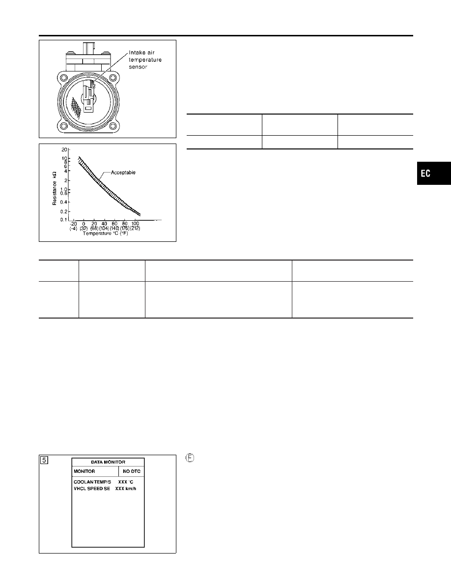
Component Description
NHEC0767
The intake air temperature sensor is mounted to the air duct hous-
ing. The sensor detects intake air temperature and transmits a sig-
nal to the ECM.
The temperature sensing unit uses a thermistor which is sensitive
to the change in temperature. Electrical resistance of the thermistor
decreases in response to the temperature rise.
<Reference data>
Intake air
temperature
°C (°F)
Voltage*
V
Resistance
k
Ω
25 (77)
3.32
1.9 - 2.1
*: These data are reference values and are measured between ECM terminal 66
(Intake air temperature sensor) and body ground.
CAUTION:
Do not use ECM ground terminals when measuring input/
output voltage. Doing so may result in damage to the ECM’s
transistor. Use a ground other than ECM terminals, such as
the ground.
On Board Diagnosis Logic
NHEC0768
DTC No.
Trouble diagnosis
name
DTC Detecting Condition
Possible Cause
P0127
0127
Intake air temperature
too high
Rationally incorrect voltage from the sensor is sent
to ECM, compared with the voltage signal from
engine coolant temperature sensor.
쐌
Harness or connectors
(The sensor circuit is open or
shorted.)
쐌
Intake air temperature sensor
DTC Confirmation Procedure
NHEC0770
NOTE:
If “DTC Confirmation Procedure” has been previously conducted,
always turn ignition switch “OFF” and wait at least 10 seconds
before conducting the next test.
CAUTION:
Always drive vehicle at a safe speed.
TESTING CONDITION:
This test may be conducted with the drive wheels lifted in the
shop or by driving the vehicle. If a road test is expected to be
easier, it is unnecessary to lift the vehicle.
SEF176Y
WITH CONSULT-II
NHEC0770S03
1)
Wait until engine coolant temperature is less than 90°C
(194°F).
a)
Turn ignition switch “ON”.
b)
Select “DATA MONITOR” mode with CONSULT-II.
c)
Check the engine coolant temperature.
d)
If the engine coolant temperature is not less than 90°C
(194°F), turn ignition switch “OFF” and cool down engine.
쐌
Perform the following steps before engine coolant temperature
is above 90°C (194°F).
2)
Turn ignition switch “ON”.
GI
MA
EM
LC
FE
AT
AX
SU
BR
ST
RS
BT
HA
SC
EL
IDX
DTC P0127 IAT SENSOR
Component Description
EC-217

3)
Select “DATA MONITOR” mode with CONSULT-II.
4)
Start engine.
5)
Hold vehicle speed at more than 70 km/h (43 MPH) for 100
consecutive seconds.
6)
If 1st trip DTC is detected, go to “Diagnostic Procedure”,
EC-218.
WITH GST
NHEC0770S04
Follow the procedure “With CONSULT-II” above.
Diagnostic Procedure
NHEC0772
1
CHECK INTAKE AIR TEMPERATURE SENSOR
Check resistance between intake air temperature sensor terminals 3 and 5 as shown in the figure.
MTBL1143
SEF012P
OK or NG
OK
䊳
GO TO 2.
NG
䊳
Replace intake air temperature sensor.
2
CHECK INTERMITTENT INCIDENT
쐌
Refer to “TROUBLE DIAGNOSIS FOR INTERMITTENT INCIDENT”, EC-151.
쐌
Refer to wiring diagram, EC-200.
䊳
INSPECTION END
DTC P0127 IAT SENSOR
DTC Confirmation Procedure (Cont’d)
EC-218

On Board Diagnosis Logic
NHEC1289
Engine coolant temperature has not risen enough to open the ther-
mostat even though the engine has run long enough.
This is due to a leak in the seal or the thermostat open stuck.
DTC No.
Trouble diagnosis
name
DTC Detecting Condition
Possible Cause
P0128
0128
Thermostat function
The engine coolant temperature does not reach to
specified temperature even though the engine has
run long enough.
쐌
Thermostat
쐌
Leakage from sealing portion of ther-
mostat
쐌
Engine coolant temperature sensor
DTC Confirmation Procedure
NHEC1291
NOTE:
If “DTC Confirmation Procedure” has been previously conducted,
always turn ignition switch “OFF” and wait at least 10 seconds
before conducting the next test.
TESTING CONDITION:
쐌
For best results, perform at ambient temperature of –10°C
(14°F) or higher.
쐌
For best results, perform at engine coolant temperature of
–10°C (14°F) to 60°C (140°F).
WITH CONSULT-II
NHEC1291S01
1)
Replace thermostat with new one. Refer to LC-18, “Thermo-
stat”. Use only a genuine NISSAN thermostat as a replace-
ment. If an incorrect thermostat is used, the MIL may come on.
2)
Turn ignition switch “ON”.
3)
Select “COOLAN TEMP/S” in “DATA MONITOR” mode with
CONSULT-II.
4)
Check that the “COOLAN TEMP/S” is above 60°C (140°F).
If it is below 60°C (140°F), go to following step.
If it is above 60°C (140°F), stop engine and cool down the
engine to less than 60°C (140°F), then retry from step 1.
5)
Drive vehicle for 10 consecutive minutes under the following
conditions.
VHCL SPEED SE
80 - 120 km/h (50 - 75 MPH)
If 1st trip DTC is detected, go to “Diagnostic Procedure”,
EC-220.
WITH GST
NHEC1291S02
1)
Follow the prodedure “WITH CONSULT-II” above.
GI
MA
EM
LC
FE
AT
AX
SU
BR
ST
RS
BT
HA
SC
EL
IDX
DTC P0128 THERMOSTAT FUNCTION
On Board Diagnosis Logic
EC-219
Diagnostic Procedure
NHEC1292
1
CHECK ENGINE COOLANT TEMPERATURE SENSOR
1. Turn ignition switch OFF.
2. Remove engine coolant temperature sensor.
3. Check resistance between engine coolant temperature sensor terminals under the following conditions.
SEF304X
OK or NG
OK
䊳
INSPECTION END
NG
䊳
Replace engine coolant temperature sensor.
DTC P0128 THERMOSTAT FUNCTION
Diagnostic Procedure
EC-220

SEF463R
SEF288D
Component Description
NHEC0873
The heated oxygen sensor 1 is placed into the front tube. It detects
the amount of oxygen in the exhaust gas compared to the outside
air. The heated oxygen sensor 1 has a closed-end tube made of
ceramic zirconia. The zirconia generates voltage from approxi-
mately 1V in richer conditions to 0V in leaner conditions. The
heated oxygen sensor 1 signal is sent to the ECM. The ECM
adjusts the injection pulse duration to achieve the ideal air-fuel
ratio. The ideal air-fuel ratio occurs near the radical change from
1V to 0V.
CONSULT-II Reference Value in Data Monitor
Mode
NHEC0874
Specification data are reference values.
MONITOR ITEM
CONDITION
SPECIFICATION
HO2S1 (B1)
HO2S1 (B2)
쐌
Engine: After warming up
Maintaining engine speed at 2,000
rpm
0 - 0.3V
+,
Approx. 0.6 - 1.0V
HO2S1 MNTR
(B1)
HO2S1 MNTR
(B2)
LEAN
+,
RICH
Changes more than 5 times during
10 seconds.
SEF301UA
On Board Diagnosis Logic
NHEC0876
To judge the malfunction, the diagnosis checks that the heated
oxygen sensor 1 output is not inordinately high.
GI
MA
EM
LC
FE
AT
AX
SU
BR
ST
RS
BT
HA
SC
EL
IDX
DTC P0132, P0152 HO2S1
Component Description
EC-221

DTC No.
Trouble diagnosis
name
DTC Detecting Condition
Possible Cause
P0132
0132
(Bank 1)
P0152
0152
(Bank 2)
Heated oxygen sen-
sor 1 circuit high volt-
age
An excessively high voltage from the sensor is
sent to ECM.
쐌
Harness or connectors
(The sensor circuit is open or
shorted.)
쐌
Heated oxygen sensor 1
SEF174Y
DTC Confirmation Procedure
NHEC0877
NOTE:
If “DTC Confirmation Procedure” has been previously conducted,
always turn ignition switch “OFF” and wait at least 10 seconds
before conducting the next test.
WITH CONSULT-II
NHEC0877S01
1)
Start engine and warm it up to normal operating temperature.
2)
Turn ignition switch “OFF” and wait at least 10 seconds.
3)
Turn ignition switch “ON”.
4)
Select “DATA MONITOR” mode with CONSULT-II.
5)
Restart engine and let it idle for 25 seconds.
6)
If 1st trip DTC is detected, go to “Diagnostic Procedure”,
EC-225.
WITH GST
NHEC0877S02
1)
Start engine and warm it up to normal operating temperature.
2)
Turn ignition switch “OFF” and wait at least 10 seconds.
3)
Restart engine and let it idle for 25 seconds.
4)
Turn ignition switch “OFF” and wait at least 10 seconds.
5)
Restart engine and let it idle for 25 seconds.
6)
Select “MODE 3” with GST.
7)
If DTC is detected, go to “Diagnostic Procedure”, EC-225.
쐌
When using GST, “DTC Confirmation Procedure” should
be performed twice as much as when using CONSULT-II
because GST cannot display MODE 7 (1st trip DTC) con-
cerning this diagnosis. Therefore, using CONSULT-II is
recommended.
DTC P0132, P0152 HO2S1
On Board Diagnosis Logic (Cont’d)
EC-222

Wiring Diagram
NHEC0878
BANK 1
NHEC0878S01
MEC537D
SEC107D
GI
MA
EM
LC
FE
AT
AX
SU
BR
ST
RS
BT
HA
SC
EL
IDX
DTC P0132, P0152 HO2S1
Wiring Diagram
EC-223

BANK 2
NHEC0878S02
MEC538D
SEC108D
DTC P0132, P0152 HO2S1
Wiring Diagram (Cont’d)
EC-224
Нет комментариевНе стесняйтесь поделиться с нами вашим ценным мнением.
Текст