Infiniti EX35. Manual — part 1388
STEERING GEAR AND LINKAGE
ST-33
< ON-VEHICLE REPAIR >
C
D
E
F
H
I
J
K
L
M
A
B
ST
N
O
P
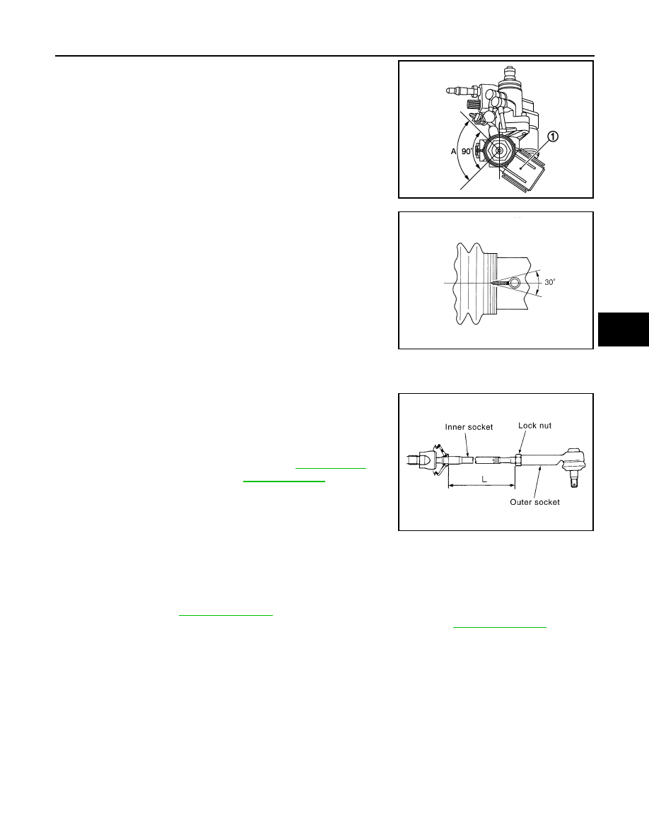
d.
Twisted area (A) of clamp is in the opposite side of adjusting
screw (1) as shown in the figure (to prevent contact with other
parts).
e.
Bent cut end of the wire toward rack axial as shown in the figure
after twisting the wire 4 to 4.5 turns so that cut end does not con-
tact with boot.
CAUTION:
Keep gap from cylinder tube 5 mm (0.20 in) or more.
19. Install cylinder tubes to gear housing assembly.
20. Install low pressure piping.
21. Adjust inner socket to standard length (L), and then tighten lock
nut to the specified torque. Check length again after tightening
lock nut.
CAUTION:
Adjust toe-in after this procedure. The length achieved after
toe-in adjustment is not necessary the above value.
2WD : Inspection
INFOID:0000000003562736
INSPECTION AFTER INSTALLATION
• Check if steering wheel turns smoothly when it is turned several times fully to the end of the left and right.
• Check the steering wheel play, neutral position steering wheel, steering wheel turning force, and front wheel
turning angle. Refer to
• Check the fluid level, fluid leakage, and air bleeding hydraulic system. Refer to
.
INSPECTION AFTER DISASSEMBLY
Boot
Check boot for cracks, and replace it if a malfunction is detected.
Rack Assembly
Check rack for damage or wear, and replace it if a malfunction is detected.
Gear-Sub Assembly
• Check gear-sub assembly for damage or wear, and replace it if a malfunction is detected.
• Rotate gear-sub assembly and check for torque variation or rattle, and replace it if a malfunction is detected.
Gear Housing Assembly
Check gear housing assembly for damage and scratches (inner wall). Replace if there are.
Outer Socket and Inner Socket
JSGIA0361ZZ
STC0124D
Standard
L
: Refer to
SGIA0167E
ST-34
< ON-VEHICLE REPAIR >
STEERING GEAR AND LINKAGE
Check the following items and replace the component if it does not meet the standard.
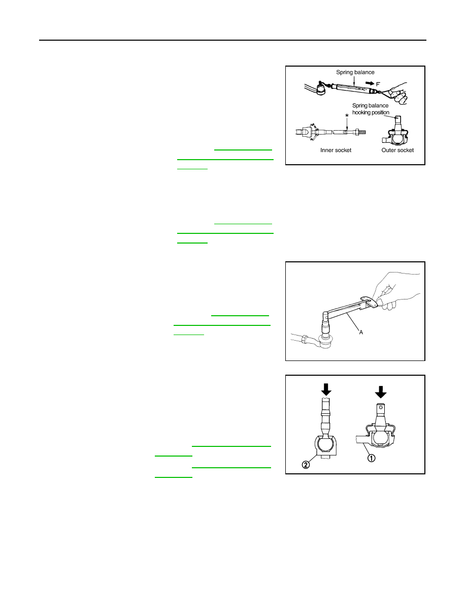
BALL JOINT SWINGING TORQUE
Hook a spring balance at the point shown in the figure and pull the
spring balance. Make sure that the spring balance reads the speci-
fied value when ball stud and inner socket start to move. Replace
outer socket and inner socket if they are outside the standard.
BALL JOINT ROTATING TORQUE
Make sure that the reading is within the following specified range
using preload gauge (A) [SST: ST3127S000 (J-25765-A)]. Replace
outer socket if the reading is outside the specified value.
BALL JOINT AXIAL END PLAY
Apply an axial load of 490 N (50 kg, 110 lb) to ball stud. Using a dial
gauge, measure amount of stud movement, and then make sure that
the value is within the following specified range. Replace outer
socket (1) and inner socket (2) if the measured value is outside the
standard.
AWD
AWD : Exploded View
INFOID:0000000003134403
REMOVAL
Standard
(Measuring point of outer socket: Stud cotter pin
mounting hole)
Outer socket
Swing Force and Rotating
Torque"
Standard
(Measuring point of inner socket: “*” mark shown in
the figure)
Inner socket
Swing Force and Rotating
Torque"
SGIA0896E
Standard
Rotating torque
: Refer to
Swing Force and Rotating
Torque"
SGIA1382E
Standard
Outer socket
: Refer to
Inner socket
: Refer to
JSGIA0109ZZ
STEERING GEAR AND LINKAGE
ST-35
< ON-VEHICLE REPAIR >
C
D
E
F
H
I
J
K
L
M
A
B
ST
N
O
P
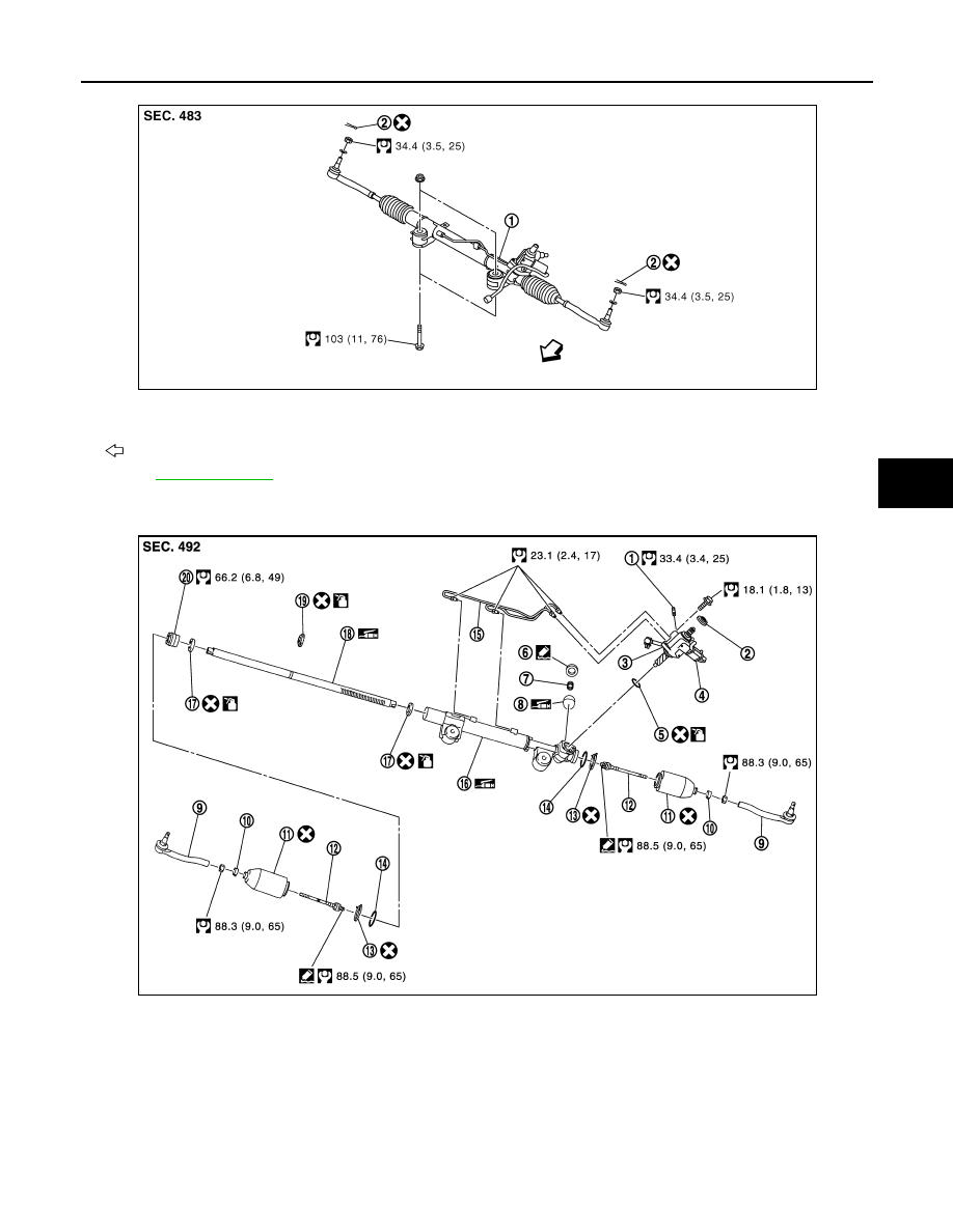
DISASSEMBLY
1.
Steering gear assembly
2.
cotter pin
: Vehicle front
Refer to
JSGIA0039GB
1.
Low pressure piping
2.
Rear cover cap
3.
Gear-sub assembly
4.
Power steering solenoid valve
5.
O-ring
6.
Adjusting screw
7.
Spring
8.
Retainer
9.
Outer socket
10. Boot clamp
11.
Boot
12. Inner socket
13. Boot clamp (stainless wire)
14. Spacer
15. Cylinder tubes
16. Gear housing assembly
17. Rack oil seal
18. Rack assembly
19. Rack Teflon ring
20. End cover assembly
JSGIA0362GB
ST-36
< ON-VEHICLE REPAIR >
STEERING GEAR AND LINKAGE
AWD : Removal and Installation
INFOID:0000000003134404
REMOVAL
1.
Set the vehicle to the straight-ahead position.
2.
Remove tires with a power tool.
3.
Remove engine lower cover and front under cover. Refer to
.
4.
Remove front cross bar. Refer to
5.
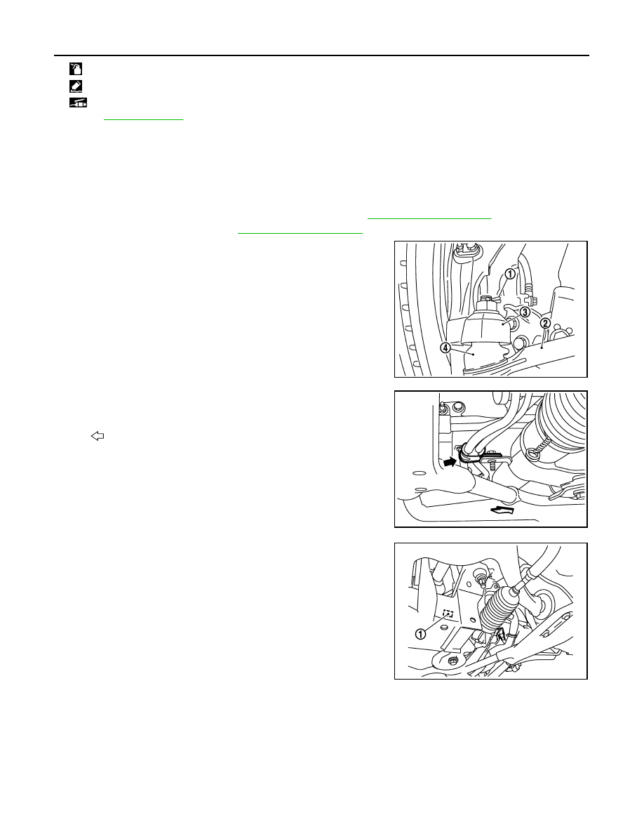
Remove cotter pin (1), and then loosen the nut.
6.
Remove steering outer socket (2) from steering knuckle (3) so
as not to damage ball joint boot (4) using suitable ball joint
remover.
CAUTION:
Temporarily tighten the nut to prevent damage to threads
and to prevent the ball joint remover from suddenly coming
off.
7.
Remove high pressure piping and low pressure piping of
hydraulic piping, and then drain power steering fluid.
8.
Remove steering hydraulic piping bracket from steering gear
assembly.
9.
Remove power steering solenoid valve harness connector (1).
10. Remove lower joint fixing bolt (steering gear side).
: Apply power steering fluid.
: Apply Genuine Liquid Gasket, Three Bond 1111B or equivalent.
: Apply multi-purpose grease.
Refer to
for symbols not described on the above.
PGIA0063E
: Vehicle front
JSGIA0043ZZ
JSGIA0363ZZ
Нет комментариевНе стесняйтесь поделиться с нами вашим ценным мнением.
Текст