Infiniti EX35. Manual — part 1383
STEERING WHEEL
ST-13
< ON-VEHICLE MAINTENANCE >
C
D
E
F
H
I
J
K
L
M
A
B
ST
N
O
P
STEERING WHEEL
Inspection
INFOID:0000000003134383
STEERING WHEEL AXIAL END PLAY
1.
Check installation conditions of steering gear assembly, front suspension assembly, axle and steering col-
umn assembly.
2.
Check if movement exists when steering wheel is moved up and down, to the left and right and to the axial
direction.
3.
Check the following items when steering wheel axial end play is out of the standard.
• Check the steering column assembly mounting condition. Refer to
(without electric motor),
ST-20, "WITH ELECTRIC MOTOR : Exploded View"
(with electric motor).
• Check steering gear assembly mounting condition for looseness. Refer to
(2WD models),
(AWD models).
STEERING WHEEL PLAY
1.
Turn steering wheel so that front wheels come to the straight-ahead position.
2.
Start the engine and lightly turn steering wheel to the left and right until front wheels start to move.
3.
Measure steering wheel movement on the outer circumference.
4.
Check the following items when steering wheel play is out of the standard.
• Check backlash for each joint of steering column assembly.
• Check installation condition of steering gear assembly.
NEUTRAL POSITION STEERING WHEEL
1.
Check that steering gear assembly, steering column assembly and steering wheel are installed in the cor-
rect position.
2.
Perform neutral position inspection after wheel alignment. Refer to
(2WD models),
(AWD models).
3.
Set the vehicle to the straight-ahead position and confirm steering wheel is in the neutral position.
4.
Loosen outer socket lock nut and turn inner socket to left and right equally to make fine adjustments if
steering wheel is not in the neutral position.
STEERING WHEEL TURNING FORCE
1.
Park the vehicle on a level and dry surface, set parking brake.
2.
Tires need to be inflated normal pressure. Refer to
3.
Start the engine.
4.
Bring power steering fluid up to adequate operating temperature.
Standard
Steering wheel axial end
play
: Refer to
Wheel Axial End Play and
Play"
.
Standard
Steering wheel play
: Refer to
Wheel Axial End Play and
Play"
.
Fluid temperature
: 50 – 80
°
C (122 – 176
°
F)
ST-14
< ON-VEHICLE MAINTENANCE >
STEERING WHEEL
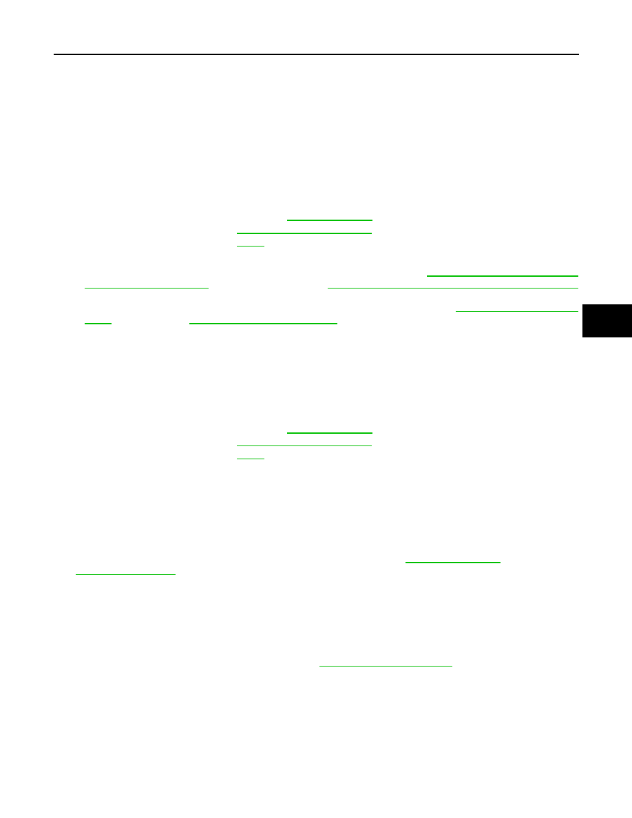
5.
Check steering wheel turning force when steering wheel has
been turned 540
°
from neutral position.
NOTE:
Multiply the distance (L) from the hook of spring balance to the
center of steering wheel by the measurement value with a spring
balance.
6.
If steering wheel turning force is out of the specification, check
rack sliding force and relief hydraulic pressure of oil pump. Regarding relief hydraulic pressure of oil
pump, refer to
.
RACK SLIDING FORCE
1.
Disconnect lower joint and steering knuckle from steering gear assembly. Refer to
(2WD models),
(AWD models).
2.
Start and run the engine at idle to make sure steering fluid has reached normal operating temperature.
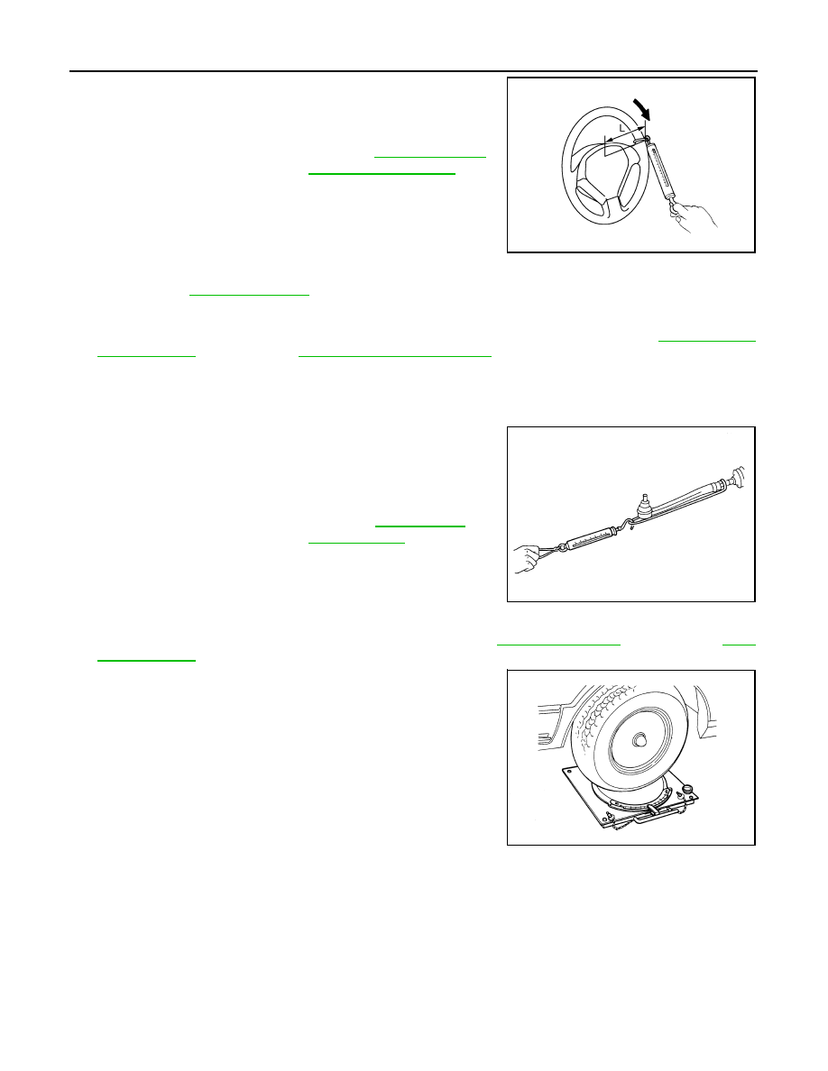
3.
While pulling outer socket slowly in
±
11.5 mm (
±
0.453 in) range
from neutral position, make sure rack sliding force is within
specification.
4.
If rack sliding force is not within specification, overhaul steering
gear assembly.
FRONT WHEEL TURNING ANGLE
1.
Check front wheel turning angle after toe-in inspection. Refer to
(2WD models),
(AWD models).
2.
Place front wheels on turning radius gauges and rear wheels on
stands, so that vehicle can be level.
3.
Check the maximum inner and outer wheel turning angles for LH
and RH road wheels.
Standard
Steering wheel turning
force
: Refer to
JSGIA0027ZZ
Fluid temperature
: 50 – 80
°
C (122 – 176
°
F)
Standard
Rack sliding force
: Refer to
.
SST090B
FAA0016D
STEERING WHEEL
ST-15
< ON-VEHICLE MAINTENANCE >
C
D
E
F
H
I
J
K
L
M
A
B
ST
N
O
P
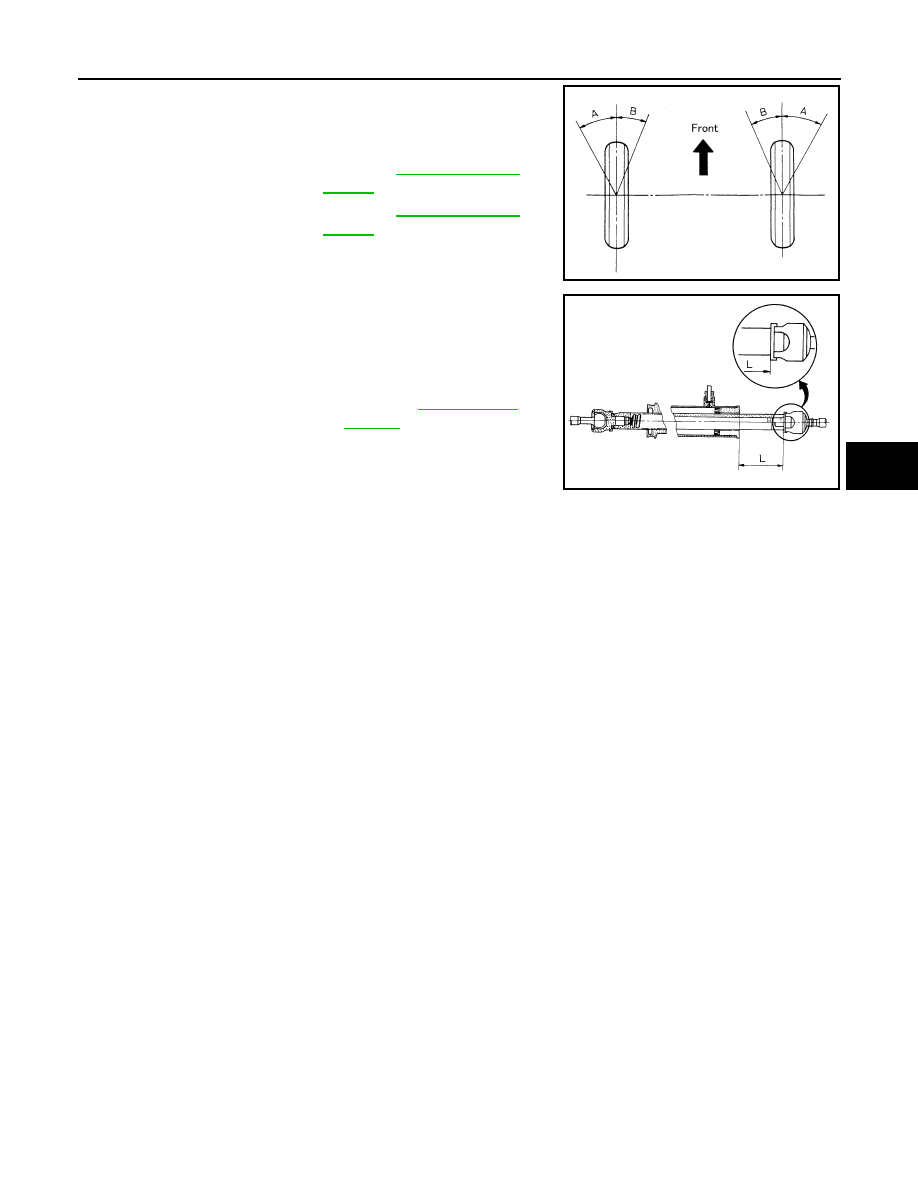
4.
With the engine at idle, turn steering wheel from full left stop to
full right stop and measure the turning angles.
5.
Check the following items when turning angle is out of the stan-
dard.
a.
Check the neutral position of the rack stroke (L).
b.
Disassemble steering gear assembly to check the cause that
rack stroke is outside of the standard.
• Steering angles are not adjustable. Check steering gear
assembly, steering column assembly and front suspension
components for wear or damage if any of the turning angles are different from the specified value.
Replace any of them, if any non-standard condition exists.
Standard
Inner wheel (Angle: A)
: Refer to
.
Outer wheel (Angle: B)
: Refer to
.
SGIA0055E
Standard
L
: Refer to
.
SGIA0629J
ST-16
< ON-VEHICLE REPAIR >
STEERING WHEEL
ON-VEHICLE REPAIR
STEERING WHEEL
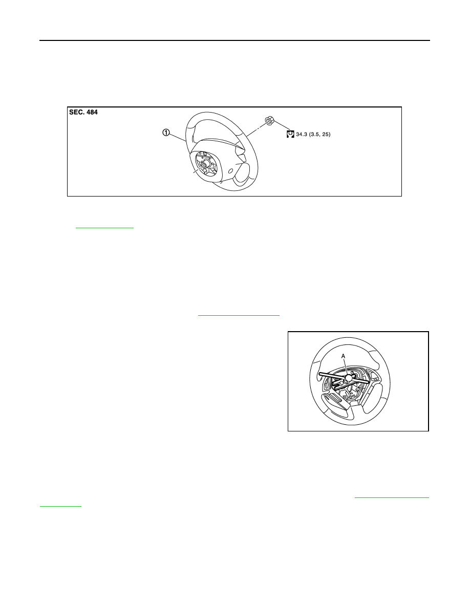
Exploded View
INFOID:0000000003134384
Removal and Installation
INFOID:0000000003134385
REMOVAL
NOTE:
When reconnecting spiral cable, fix cable with a tape so that fixing case and rotating part keep aligned. This
will omit neutral position alignment procedure during spiral cable installation.
1.
Set the vehicle to the straight-ahead position.
2.
Remove driver air bag module. Refer to
.
3.
Remove steering wheel lock nut after steering is locked.
4.
Remove steering wheel with the steering wheel puller (A) [SST:
ST27180001 (J-25726-A)].
INSTALLATION
Note the following, and install in the reverse order of removal.
CAUTION:
Never twist spiral cable freely on excessively after it becomes tight (doing so may cause the cable to
tear off).
NOTE:
Check the spiral cable neutral position after replacing or rotating spiral cable. Refer to
1.
Steering wheel
Refer to
for symbols in the figure.
JSGIA0340GB
JSGIA0341ZZ
Нет комментариевНе стесняйтесь поделиться с нами вашим ценным мнением.
Текст