Infiniti EX35. Manual — part 345
ABS ACTUATOR AND ELECTRIC UNIT (CONTROL UNIT)
BRC-95
< ECU DIAGNOSIS >
[VDC/TCS/ABS]
C
D
E
G
H
I
J
K
L
M
A
B
BRC
N
O
P
• For malfunction of ABS, only the EBD is activated and the condition of vehicle is the same condition of vehi-
cles without TCS/ABS system.
NOTE:
ABS self-diagnosis sound may be heard. That is a normal condition because a self-diagnosis for “Ignition
switch ON” and “The first starting” are being performed.
• For malfunction of EBD, EBD and ABS become inoperative, and the condition of vehicle is the same as the
condition of vehicles without TCS/ABS, EBD system.
VDC / TCS
If VDC/TCS/ABS system malfunction electrically, VDC OFF indicator lamp, SLIP indicator lamp are turned on,
and the condition of vehicle is the same as the condition of vehicles without VDC/TCS control.
CAUTION:
If the Fail-Safe function is activated, then perform self-diagnosis for VDC/TCS/ABS control system.
LDW/LDP SYSTEM
• In case of malfunction in the LDW/LDP system, lane departure warning lamp is turned ON, and the condition
of vehicle is the same as the condition of vehicles without LDW/LDP control.
• In case of malfunction in the VDC/TCS/ABS system, lane departure warning lamp is turned ON, and the
condition of vehicle is the same as the condition of vehicles without LDW/LDP control.
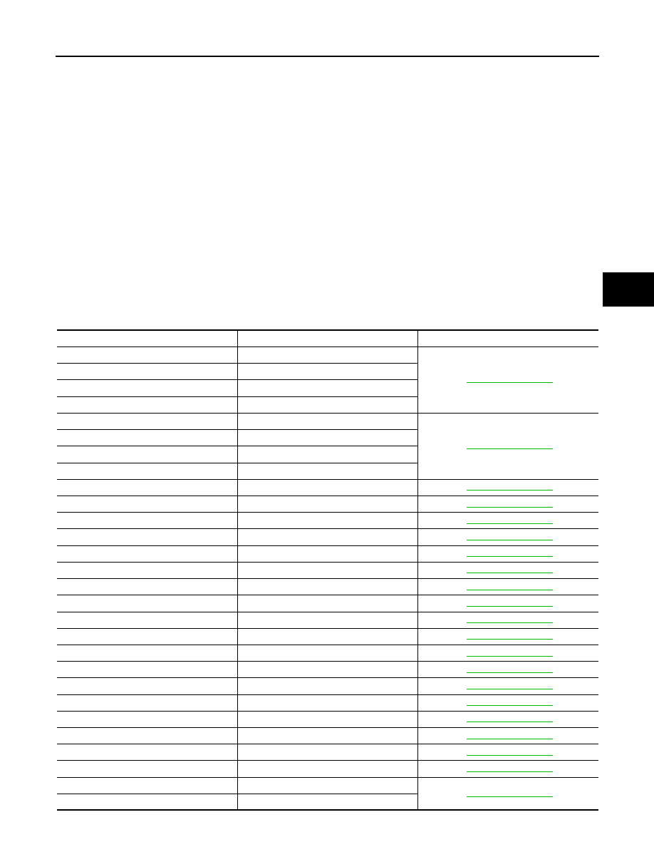
DTC No. Index
INFOID:0000000003132987
DTC
Items (CONSULT screen terms)
Reference
C1101
RR RH SENSOR-1
C1102
RR LH SENSOR-1
C1103
FR RH SENSOR-1
C1104
FR LH SENSOR-1
C1105
RR RH SENSOR-2
C1106
RR LH SENSOR-2
C1107
FR RH SENSOR-2
C1108
FR LH SENSOR-2
C1109
BATTERY VOLTAGE [ABNORMAL]
C1110
CONTROLLER FAILURE
C1111
PUMP MOTOR
C1114
MAIN RELAY
C1115
ABS SENSOR [ABNORMAL SIGNAL]
C1116
STOP LAMP SW
C1120
FR LH IN ABS SOL
C1121
FR LH OUT ABS SOL
C1122
FR RH IN ABS SOL
C1123
FR RH OUT ABS SOL
C1124
RR LH IN ABS SOL
C1125
RR LH OUT ABS SOL
C1126
RR RH IN ABS SOL
C1127
RR RH OUT ABS SOL
C1130
ENGINE SIGNAL 1
C1142
PRESS SEN CIRCUIT
C1143
ST ANG SEN CIRCUIT
C1144
ST ANG SEN SIGNAL
C1145
YAW RATE SENSOR
C1146
SIDE G-SEN CIRCUIT
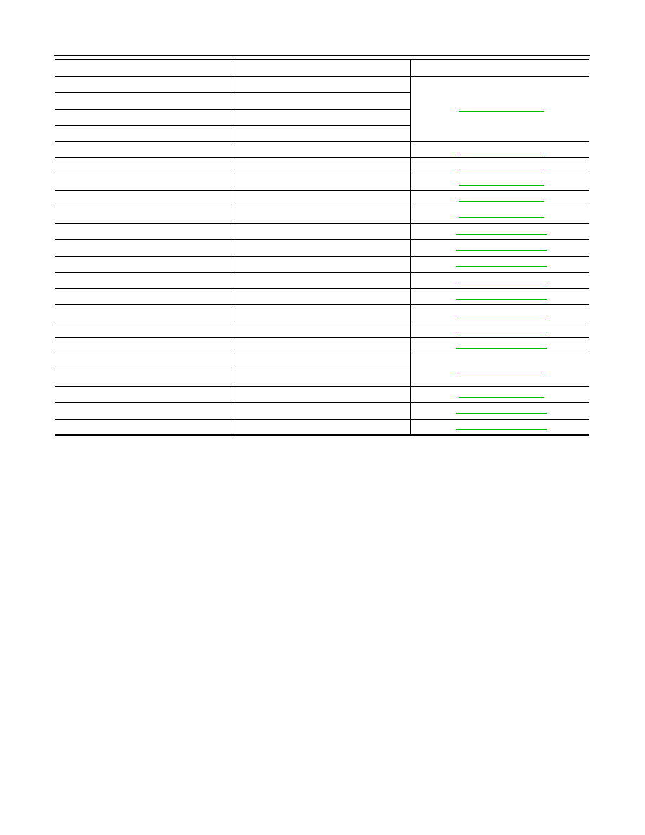
BRC-96
< ECU DIAGNOSIS >
[VDC/TCS/ABS]
ABS ACTUATOR AND ELECTRIC UNIT (CONTROL UNIT)
C1147
USV LINE [FL-RR]
C1148
USV LINE [FR-RL]
C1149
HSV LINE [FL-RR]
C1150
HSV LINE [FR-RL]
C1153
EMERGENCY BRAKE
C1154
PNP POSI SIG
C1155
BR FLUID LEVEL LOW
C1170
VARIANT CORDING
C1185
ACC CONT
C1B00
LDP) CAMERA MALF
C1B04
LDP) ICC STG SW MALF
C1B05
LDP) APP SEN MALF
C1B06
LDP) TCM MALF
U0100
LDP) ECM CAN CIR2
U0101
LDP) TCM CAM CAN CIR2
U0104
LDP) ICC CAM CAN CIR2
U0405
LDP) ICC CAM CAN CIR1
U1000
CAN COMM CIRCUIT
U1002
SYSTEM COMM (CAN)
U1100
ACC COMM CIRCUIT
U1500
LDP) CAM CAN CIR1
U1501
LDP) CAM CAN CIR2
DTC
Items (CONSULT screen terms)
Reference
EXCESSIVE ABS FUNCTION OPERATION FREQUENCY
BRC-97
< SYMPTOM DIAGNOSIS >
[VDC/TCS/ABS]
C
D
E
G
H
I
J
K
L
M
A
B
BRC
N
O
P
SYMPTOM DIAGNOSIS
EXCESSIVE ABS FUNCTION OPERATION FREQUENCY
Diagnosis Procedure
INFOID:0000000003132989
1.
CHECK START
Check front and rear brake force distribution using a brake tester. Refer to
BR-46, "General Specifications"
.
Is the inspection result normal?
YES
>> GO TO 2.
NO
>> Check brake system.
2.
CHECK FRONT AND REAR AXLE
Make sure that there is no excessive play in the front and rear axles.
• Front
- 2WD models: Refer to
- AWD models: Refer to
• Rear: Refer to
Is the inspection result normal?
YES
>> GO TO 3.
NO
>> Repair or replace malfunctioning components.
3.
CHECK WHEEL SENSOR AND SENSOR ROTOR
Check the following.
• Wheel sensor installation for damage.
• Sensor rotor installation for damage.
• Wheel sensor connector connection.
• Wheel sensor harness inspection.
Is the inspection result normal?
YES
>> GO TO 4.
NO
>> • Replace wheel sensor or sensor rotor.
• Repair harness.
4.
CHECK ABS WARNING LAMP DISPLAY
Make sure that the ABS warning lamp is turned off after the ignition switch is turned ON or when driving.
Is the ABS warning lamp illuminated?
YES
>> Perform self-diagnosis.
NO
>> Normal
BRC-98
< SYMPTOM DIAGNOSIS >
[VDC/TCS/ABS]
UNEXPECTED PEDAL REACTION
UNEXPECTED PEDAL REACTION
Diagnosis Procedure
INFOID:0000000003132990
1.
CHECK BRAKE PEDAL STROKE
Check brake pedal stroke. Refer to
BR-7, "Inspection and Adjustment"
Is the stroke too large?
YES
>> • Bleed air from brake tube and hose. Refer to
BR-11, "Bleeding Brake System"
• Check brake pedal, brake booster, and master cylinder for mount play, looseness, brake system
fluid leakage, etc.
- Brake pedal: Refer to
BR-7, "Inspection and Adjustment"
.
- Brake booster: Refer to
- Master cylinder: Refer to
.
NO
>> GO TO 2.
2.
CHECK FUNCTION
Disconnect ABS actuator and electric unit (control unit) connector to deactivate ABS. Check if braking force is
normal in this condition. Connect connector after inspection.
Is the inspection result normal?
YES
>> Normal
NO
>> Check brake system.
Нет комментариевНе стесняйтесь поделиться с нами вашим ценным мнением.
Текст