Infiniti EX35. Manual — part 1221
POWER SUPPLY AND GROUND CIRCUIT
RF-9
< COMPONENT DIAGNOSIS >
C
D
E
F
G
H
I
J
L
M
A
B
RF
N
O
P
COMPONENT DIAGNOSIS
POWER SUPPLY AND GROUND CIRCUIT
BCM (BODY CONTROL MODULE)
BCM (BODY CONTROL MODULE) : Diagnosis Procedure
INFOID:0000000003703350
1.
CHECK FUSE AND FUSIBLE LINK
1.Turn ignition switch OFF.
2.Check that the following fuse and fusible link are not blown.
Is the fuse fusing?
YES
>> Replace the blown fuse or fusible link after repairing the affected circuit if a fuse or fusible link is
blown.
NO
>> GO TO 2.
2.
CHECK POWER SUPPLY CIRCUIT
1.
Disconnect BCM connectors.
2.
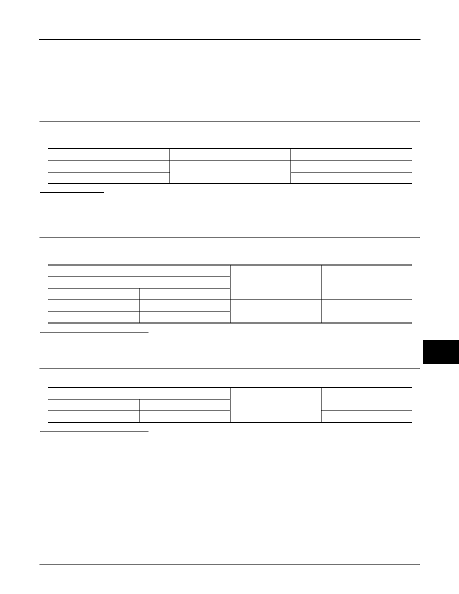
Check voltage between BCM harness connector and ground.
Is the inspection result normal?
YES
>> GO TO 3.
NO
>> Repair or replace harness or connector.
3.
CHECK GROUND CIRCUIT
Check continuity between BCM harness connector and ground.
Is the inspection result normal?
YES
>> INSPECTION END
NO
>> Repair or replace harness or connector.
SUNROOF MOTOR ASSEMBLY
SUNROOF MOTOR ASSEMBLY : Description
INFOID:0000000003601788
• BCM supplies power.
• It is sunroof motor and CPU integrated type.
• Tilt up/down & slide open/close by sunroof switch operation.
SUNROOF MOTOR ASSEMBLY : Diagnosis Procedure
INFOID:0000000003601789
SUNROOF MOTOR ASSEMBLY
1.
CHECK POWER SUPPLY CIRCUIT
Terminal No.
Signal name
Fuse and fusible link No.
1
Battery power supply
K (40A)
11
10 (10A)
(+)
(
−
)
Voltage
(Approx.)
BCM
Connector
Terminal
M118
1
Ground
Battery voltage
M119
11
BCM
Ground
Continuity
Connector
Terminal
M119
13
Existed
RF-10
< COMPONENT DIAGNOSIS >
POWER SUPPLY AND GROUND CIRCUIT
1.
Turn ignition switch OFF.
2.
Disconnect sunroof motor assembly connector.
3.
Turn ignition switch ON.
4.
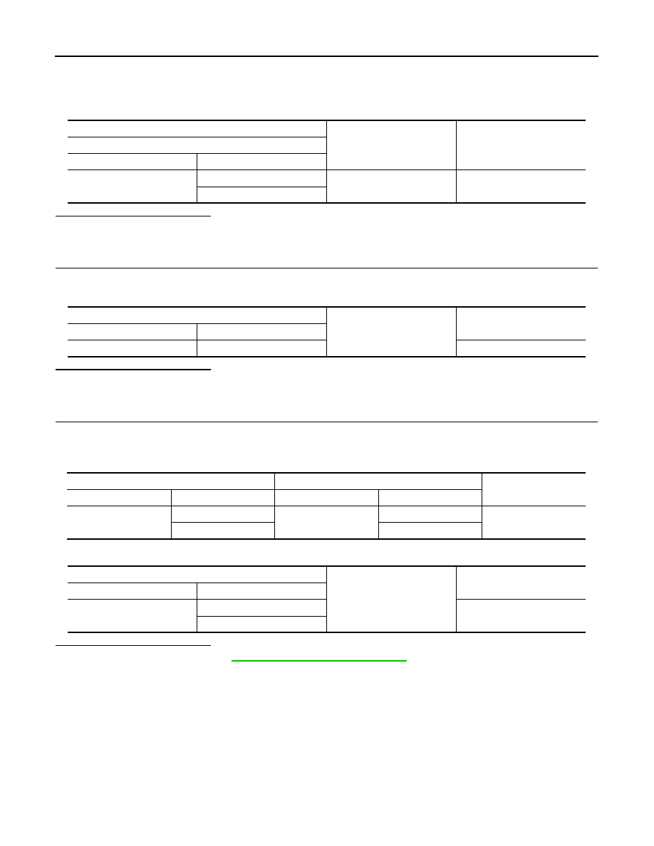
Check voltage between sunroof motor assembly harness connector and ground.
Is the inspection result normal?
YES
>> GO TO 2.
NO
>> GO TO 3.
2.
CHECK GROUND CIRCUIT
1.
Turn ignition switch OFF.
2.
Check continuity between sunroof motor assembly harness connector and ground.
Is the inspection result normal?
YES
>> INSPECTION END
NO
>> Repair or replace harness or connector.
3.
CHECK SUNROOF MOTOR CIRCUIT
1.
Turn ignition switch OFF.
2.
Disconnect BCM connector.
3.
Check continuity between BCM harness connector and sunroof motor assembly harness connector.
4.
Check continuity between BCM harness connector and ground.
Is the inspection result normal?
YES
>> Replace BCM.Refer to
BCS-84, "Removal and Installation"
.
NO
>> Repair or replace harness or connector.
(+)
(–)
Voltage (V)
(Approx.)
Sunroof motor assembly
Connector
Terminal
R4
9
Ground
Battery voltage
7
Sunroof motor assembly
Ground
Continuity
Connector
Terminal
R4
10
Exists
BCM
Sunroof motor assembly
Continuity
Connector
Terminal
Connector
Terminal
M118
2
R4
7
Exists
3
9
BCM
Ground
Continuity
Connector
Terminal
M118
2
Not exist
3
SUNROOF SWITCH
RF-11
< COMPONENT DIAGNOSIS >
C
D
E
F
G
H
I
J
L
M
A
B
RF
N
O
P
SUNROOF SWITCH
Description
INFOID:0000000003601790
Tilt up/down & slide open/close by sunroof switch operation.
Component Function Check
INFOID:0000000003601791
1.
CHECK SUNROOF MOTOR OPERATION
Check tilt up/down & slide open/close operations with sunroof switch.
Is the inspection result normal?
YES
>> Sunroof switch is OK.
NO
>> Refer to
Diagnosis Procedure
INFOID:0000000003601792
SUNROOF SWITCH
1.
CHECK SUNROOF SWITCH POWER SUPPLY CIRCUIT
1.
Turn ignition switch OFF.
2.
Disconnect sunroof switch connector.
3.
Turn ignition switch ON.
4.
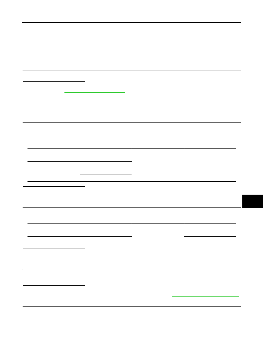
Check voltage between sunroof switch harness connector and ground.
Is the inspection result normal?
YES
>> GO TO 2.
NO
>> GO TO 4.
2.
CHECK GROUND CIRCUIT
1.
Turn ignition switch OFF.
2.
Check continuity between sunroof switch harness connector and ground.
Is the inspection result normal?
YES
>> GO TO 3.
NO
>> Repair or replace harness or connector.
3.
CHECK SUNROOF SWITCH
Check sunroof switch.
Refer to
Is the inspection result normal?
YES
>> GO TO 5.
NO
>> Replace sunroof switch (built in map lamp assembly). Refer to
RF-83, "Removal and Installation"
.
4.
CHECK SUNROOF SWITCH CIRCUIT
1.
Turn ignition switch OFF.
2.
Disconnect sunroof motor assembly connector.
3.
Check continuity between sunroof switch assembly harness connector and sunroof switch harness con-
nector.
(+)
(–)
Voltage (V)
(Approx.)
Sunroof switch
Connector
Terminal
R16
1
Ground
Battery voltage
3
Sunroof switch
Ground
Continuity
Connector
Terminal
R16
2
Exist
RF-12
< COMPONENT DIAGNOSIS >
SUNROOF SWITCH
4.
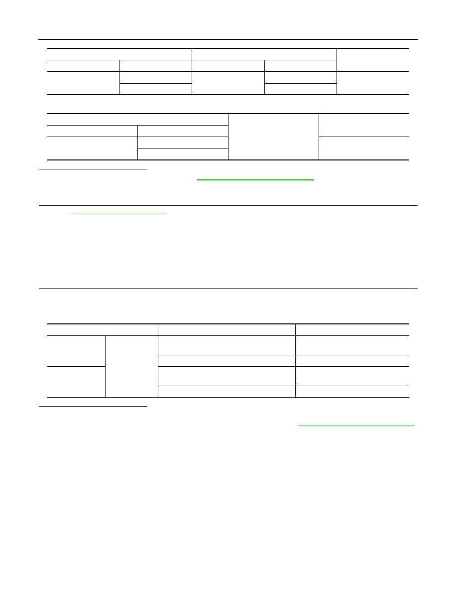
Check continuity between sunroof switch assembly harness connector and ground.
Is the inspection result normal?
YES
>> Replace sunroof motor assembly.
RF-75, "Removal and Installation"
NO
>> Repair or replace harness or connector.
5.
CHECK INTERMITTENT INCIDENT
GI-38, "Intermittent Incident"
>> INSPECTION END
Component Inspection
INFOID:0000000003601793
SUNROOF SWITCH
1.
CHECK SUNROOF SWITCH
1.
Turn ignition switch OFF.
2.
Disconnect sunroof switch connector.
3.
Check continuity sunroof switch terminals.
Is the inspection result normal?
YES
>> INSPECTION END
NO
>> Replace sunroof switch (built in map lamp assembly). Refer to
RF-83, "Removal and Installation"
.
Sunroof switch
Sunroof motor assembly
Continuity
Connector
Terminal
Connector
Terminal
R16
1
R4
5
Exist
3
1
Sunroof motor assembly
Ground
Continuity
Connector
Terminal
R4
5
Not exist
1
Terminals
Condition
Continuity
1
2
Sunroof switch is operated
TILT DOWN or SLIDE OPEN
Exists
Other than above
Not exist
3
Sunroof switch is operated
TILT UP or SLIDE CLOSE
Exists
Other than above
Not exist
Нет комментариевНе стесняйтесь поделиться с нами вашим ценным мнением.
Текст