Infiniti EX35. Manual — part 168
AV
AUDIO SYSTEM
AV-453
< FUNCTION DIAGNOSIS >
[BOSE AUDIO WITH NAVIGATION]
C
D
E
F
G
H
I
J
K
L
M
B
A
O
P
AUDIO SYSTEM
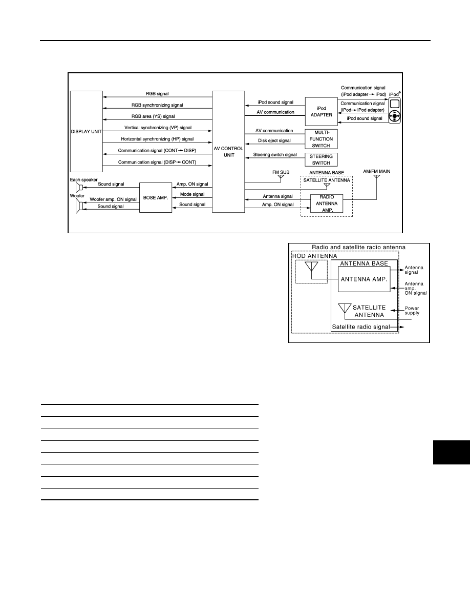
System Diagram
INFOID:0000000003160603
NOTE:
A radio antenna base integrated with radio antenna and satellite
radio antenna is adopted.
System Description
INFOID:0000000003515921
The audio system is equipped with the following functions. Each function is operated by multifunction switch,
preset switch, touch panel, steering switch or audio recognition. Operation status of AUDIO is indicated at dis-
play.
FUNCTION DESCRIPTION
Operating signal
Audio system operation can be performed with multifunction switch, preset switch, steering switch, touch
panel function or voice recognition function.
• Operating signal is transmitted to AV control unit with AV communication when it is operated by multifunction
switch or preset switch. The disk ejection operating signal is performed by hardwire.
• Operating signal is transmitted to AV control unit with steering switch signal when it is operated by steering
switch.
JSNIA0703GB
JSNIA1062GB
Function
AM/FM radio
Satellite radio
CD
Music Box (Hard Disk Drive)
CF (Compact Flash)
iPod connection
Driver's Audio Stage
AV-454
< FUNCTION DIAGNOSIS >
[BOSE AUDIO WITH NAVIGATION]
AUDIO SYSTEM
• Refer to
for explanation of voice recognition function and touch panel function.
Screen display
• The display is switched by communication signal between display and AV control unit.
• The image signal that displays operating status is performed by the RGB signal, RGB area signal and RGB
image synchronizing signal.
AM/FM Radio Mode
• AM/FM radio tuner is built into AV control unit.
• Audio signal is received by rod antenna, next it is amplified by antenna amp., and finally it is input into AV
control unit. The FM sub antenna is installed on the back door window glass and AV control unit receives
audio signal.
• Audio signal is input to BOSE amp. and BOSE amp. outputs to woofer and each speakers for AV control
unit.
Satellite Radio Mode
• Satellite radio tuner is built into AV control unit.
• Audio signal (satellite radio) is received by satellite antenna, and it is input to AV control unit. AV control unit
outputs audio signal to BOSE amp. The signal is also outputted from BOSE amp. to both woofer and each
speaker.
CD Mode
• CD function is built into AV control unit.
• AV control unit outputs audio signals to BOSE amp. and BOSE amp. outputs to woofer and each speaker
when CD is inserted to AV control unit.
Music Box Mode
• Music CD data is stored on HDD that is built into AV control unit, and it can be played.
• AV control unit outputs music (audio signal) that is stored on HDD to BOSE amp., and BOSE amp. outputs to
woofer and each speaker.
CF Mode
• AV control unit has built in CF replay function.
• Music (audio signal) that is stored in CF outputs to BOSE amp. and BOSE amp. outputs to woofer and each
speaker when CF is inserted into AV control unit.
iPod Connection
• Connect iPod
®
and iPod adapter with wire harness and iPod adapter inputs iPod sound signal from iPod
®
.
When iPod mode is selected, iPod adapter outputs iPod sound signal to AV control unit. AV control unit out-
puts sound signal to BOSE amp., and BOSE amp. output sound signal to woofer and each speaker.
• Receiving/transmitting of iPod
®
operation signals are performed as follows:
- between AV control unit and iPod adapter: AV communication.
- between iPod
®
and iPod adapter: serial communication.
• The iPod
®
connection status can be recognized whether iPod adapter receives iPod connection recognition
signal.
• The iPod adapter can charge iPod
®
.
Driver's Audio Stage Mode
• Driver's Audio Stage controls the speaker's output characteristics by BOSE amp. so that the driver seat is
the center of sound.
• ON/OFF signals of Driver's Audio Stage are transmitted from AV control unit to BOSE amp. using Mode sig-
nal.

AV
AUDIO SYSTEM
AV-455
< FUNCTION DIAGNOSIS >
[BOSE AUDIO WITH NAVIGATION]
C
D
E
F
G
H
I
J
K
L
M
B
A
O
P
Component Parts Location
INFOID:0000000003579816
1.
Center speaker
2.
Corner sensor front RH
3.
Front squawker LH
4.
Front camera
5.
Corner sensor front LH
6.
Side camera LH
JPNIA0911ZZ

AV-456
< FUNCTION DIAGNOSIS >
[BOSE AUDIO WITH NAVIGATION]
AUDIO SYSTEM
Component Description
INFOID:0000000003515970
7.
Front door speaker LH
8.
• Around view monitor control unit
(with around view monitor)
• Camera control unit (with rear view
monitor)
9.
Rear door speaker LH
10. Rear squawker LH
11. BOSE amp.
12. Corner sensor rear LH
13. Woofer
14. • Rear camera (with around view
monitor)
• Rear view camera (with rear view
monitor)
15. Corner sensor rear RH
16. Buzzer
17. Rear squawker RH
18. Antenna base (antenna amp and sat-
ellite antenna)
19. Rear door speaker RH
20. Side camera RH
21. Front door speaker RH
22. Front squawker RH
23. Display unit
24. Steering angle sensor
25. Steering switch
26. Preset switch
27. Sonar control unit (with around view
monitor)
28. iPod connector
29. Auxiliary input jacks
30. AV control unit
31. Multifunction switch
32. iPod adapter
33. GPS antenna
34. Microphone
A.
Under front seat (LH side)
B.
Luggage floor (LH side)
C.
Luggage side RH
D.
Spiral cable part
E.
Cluster lid C removed condition
F.
Rear view of the display unit
G.
Instrument panel rear side
Part name
Description
AV CONTROL UNIT
• Receiving function of AM/FM/satellite radio, replaying function of CD, replay-
ing/saving functions of music box (HDD), replaying function of CF and voice
recognition function are integrated.
• Audio signal is output to BOSE amp. from each function.
DISPLAY UNIT
• Display image is controlled by the serial communication from AV control unit.
• RGB image signal (audio operation condition) is input from AV control unit.
• Touch panel function can be operated for each system by touching the display
directly.
BOSE AMP.
• Inputs power (amp. ON) and sound signal from AV control unit, and outputs
sound signal to woofer and each speaker.
• Input “Driver's Audio Stage” mode change signal from AV control unit.
• Woofer amp. ON signal is transmitted to woofer.
FRONT DOOR SPEAKER
• Outputs sound signal from BOSE amp.
• Outputs sound (mid and low range).
REAR DOOR SPEAKER
• Outputs sound signal from BOSE amp.
• Outputs sound (mid and low range).
FRONT SQUAWKER
• Outputs sound signal from BOSE amp.
• Outputs sound (high and mid range).
REAR SQUAWKER
• Outputs sound signal from BOSE amp.
• Outputs sound (high and mid range).
CENTER SPEAKER
• Outputs sound signal from BOSE amp.
• Outputs sound (high and mid range).
WOOFER
• Inputs power (amp. ON) and sound signals from BOSE amp.
• Outputs low-frequency sound.
MULTIFUNCTION SWITCH
• Each audio operation can be operated.
• Connected with preset switch via cable, and operation signal is transmitted to
AV control unit via AV communication.
PRESET SWITCH
• Each audio operation can be operated.
• Connected with multifunction switch via cable, and operation signal is transmit-
ted to AV control unit via AV communication.
• The disk ejection operating signal is performed by hardwire.
Нет комментариевНе стесняйтесь поделиться с нами вашим ценным мнением.
Текст