Infiniti EX35. Manual — part 1333
SN
POWER SUPPLY AND GROUND CIRCUIT
SN-23
< COMPONENT DIAGNOSIS >
C
D
E
F
G
H
I
J
K
L
M
B
A
O
P
POWER SUPPLY AND GROUND CIRCUIT
SONAR CONTROL UNIT
SONAR CONTROL UNIT : Diagnosis Procedure
INFOID:0000000003160568
1.
CHECK FUSE
Check for blown fuses.
Is the inspection result normal?
YES
>> GO TO 2.
NO
>> Be sure to eliminate cause of malfunction before installing new fuse.
2.
CHECK POWER SUPPLY CIRCUIT
1.
Turn ignition switch ON.
2.
Check voltage between sonar control unit harness connector and ground.
Is the inspection result normal?
YES
>> GO TO 3.
NO
>> Repair or replace sonar control unit power supply harness.
3.
CHECK GROUND CIRCUIT
1.
Turn ignition switch OFF.
2.
Disconnect sonar control unit connector.
3.
Check continuity between sonar control unit harness connector and ground.
Is the inspection result normal?
YES
>> INSPECTION END
NO
>> Repair or replace sonar control unit ground harness.
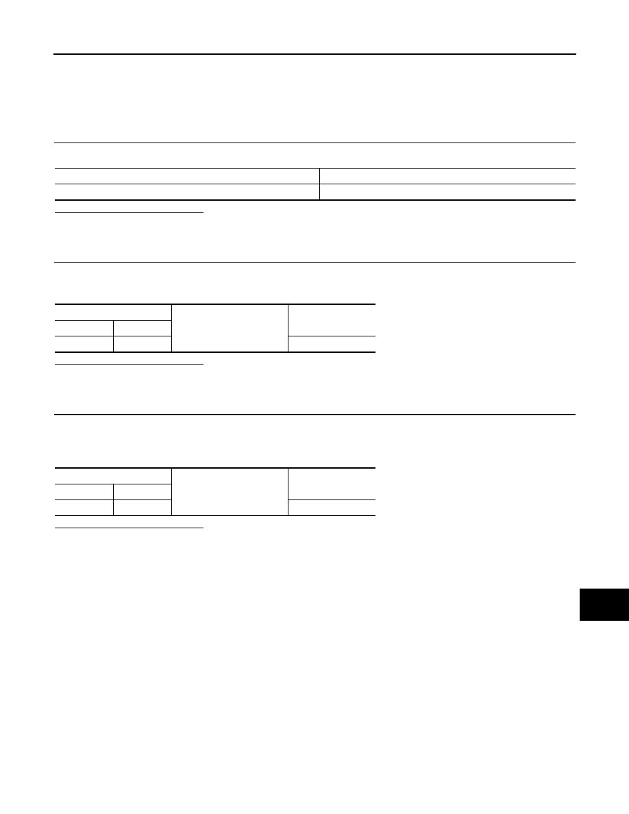
Power source
Fuse No.
Ignition switch ON or START
3
Sonar control unit
Ground
Voltage
(Approx.)
Connector
Terminal
M44
13
Battery voltage
Sonar control unit
Ground
Continuity
Connector
Terminal
M44
24
Existed
SN-24
< COMPONENT DIAGNOSIS >
P RANGE SIGNAL CIRCUIT
P RANGE SIGNAL CIRCUIT
Description
INFOID:0000000003160569
The sonar control unit turns the sonar system activation OFF when inputting P range signal.
Component Function Check
INFOID:0000000003160570
1.
SONAR CONTROL UNIT DATA MONITOR INSPECTION
Check the cancel switch with the sonar control unit data monitor.
P range
>> INSPECTION END
Diagnosis Procedure
INFOID:0000000003160571
1.
CHECK P RANGE SIGNAL
1.
Turn ignition switch ON.
2.
Check voltage between sonar control unit harness connector and ground.
Is the inspection result normal?
YES
>> INSPECTION END
NO
>> Repair harness or connector.
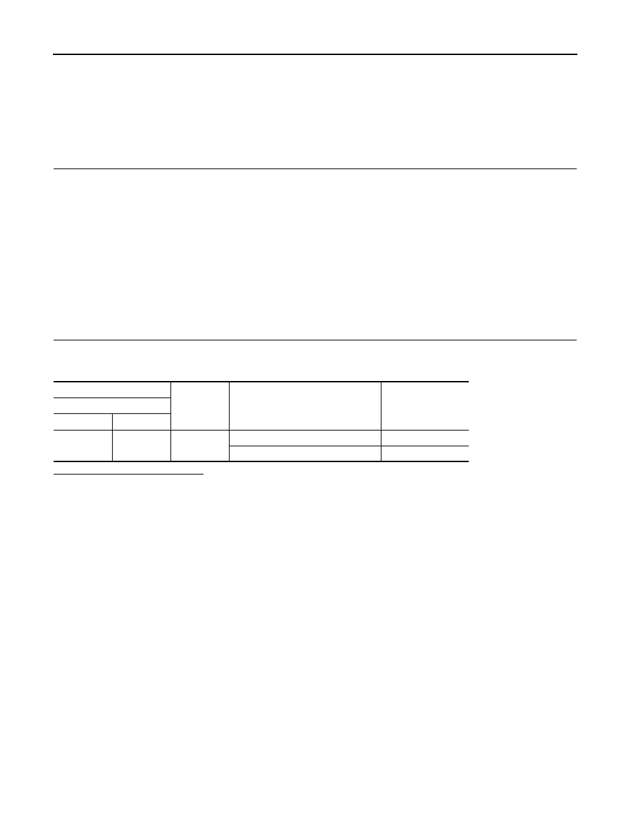
Vehicle condition
Indication
Shift position in P position
: ON
Other than shift position in
P position
: OFF
(+)
(
−
)
Condition
Voltage
(Approx.)
Sonar control unit
Connector
Terminal
M44
16
Ground
Shift position in P position.
0 V
Other than shift position in P position.
12.0 V
SN
R RANGE SIGNAL CIRCUIT
SN-25
< COMPONENT DIAGNOSIS >
C
D
E
F
G
H
I
J
K
L
M
B
A
O
P
R RANGE SIGNAL CIRCUIT
Description
INFOID:0000000003160572
The sonar control unit turns the sonar system activation OFF when inputting the reverse signal.
Component Function Check
INFOID:0000000003160573
1.
SONAR CONTROL UNIT DATA MONITOR INSPECTION
Check the cancel switch with the sonar control unit data monitor.
R range
>> INSPECTION END
Diagnosis Procedure
INFOID:0000000003160574
1.
CHECK P RANGE SIGNAL
1.
Turn ignition switch ON.
2.
Check voltage between sonar control unit harness connector and ground.
Is the inspection result normal?
YES
>> INSPECTION END
NO
>> Repair harness or connector.
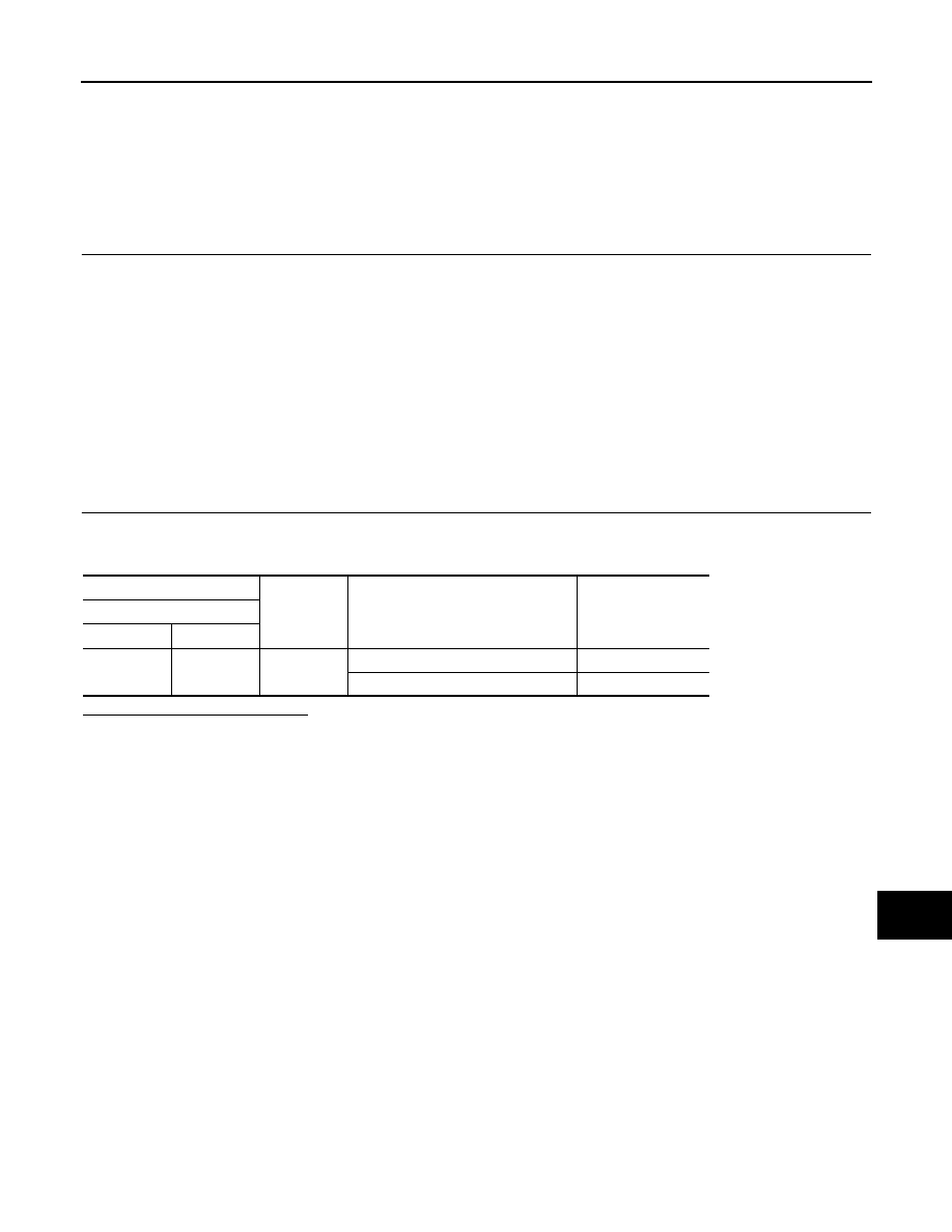
Vehicle condition
Indication
Shift position in R position
: ON
Other than shift position in
R position
: OFF
(+)
(
−
)
Condition
Voltage
(Approx.)
Sonar control unit
Connector
Terminal
M44
17
Ground
Shift position in R position.
12.0 V
Other than shift position in R position.
0 V
SN-26
< COMPONENT DIAGNOSIS >
BUZZER CIRCUIT
BUZZER CIRCUIT
Description
INFOID:0000000003160575
The sonar control unit outputs the buzzer signal when the rear sonar detects the obstacle.
Component Function Check
INFOID:0000000003160576
1.
SONAR CONTROL UNIT ACTIVE TEST
Check the buzzer operation with the sonar control unit active test.
BUZZER
>> INSPECTION END
Diagnosis Procedure
INFOID:0000000003160577
1.
CHECK BUZZER POWER SUPPLY
1.
Turn ignition switch ON.
2.
Check voltage between buzzer harness connector and ground.
Is the inspection result normal?
YES
>> GO TO 2.
NO
>> Repair harness or connector.
2.
CHECK HARNESS BUZZER SIGNAL CIRCUIT
1.
Turn ignition switch OFF.
2.
Disconnect sonar control unit connector and buzzer connector.
3.
Check continuity between sonar control unit harness connector and buzzer harness connector.
4.
Check continuity between sonar control unit harness connector and ground.
Is the inspection result normal?
YES
>> GO TO 3.
NO
>> Repair harness or connector.
3.
CHECK SIGNAL SONAR CONTROL UNIT
1.
Connect sonar control unit connector and buzzer connector.
2.
Check signal between sonar control unit harness connector and ground.
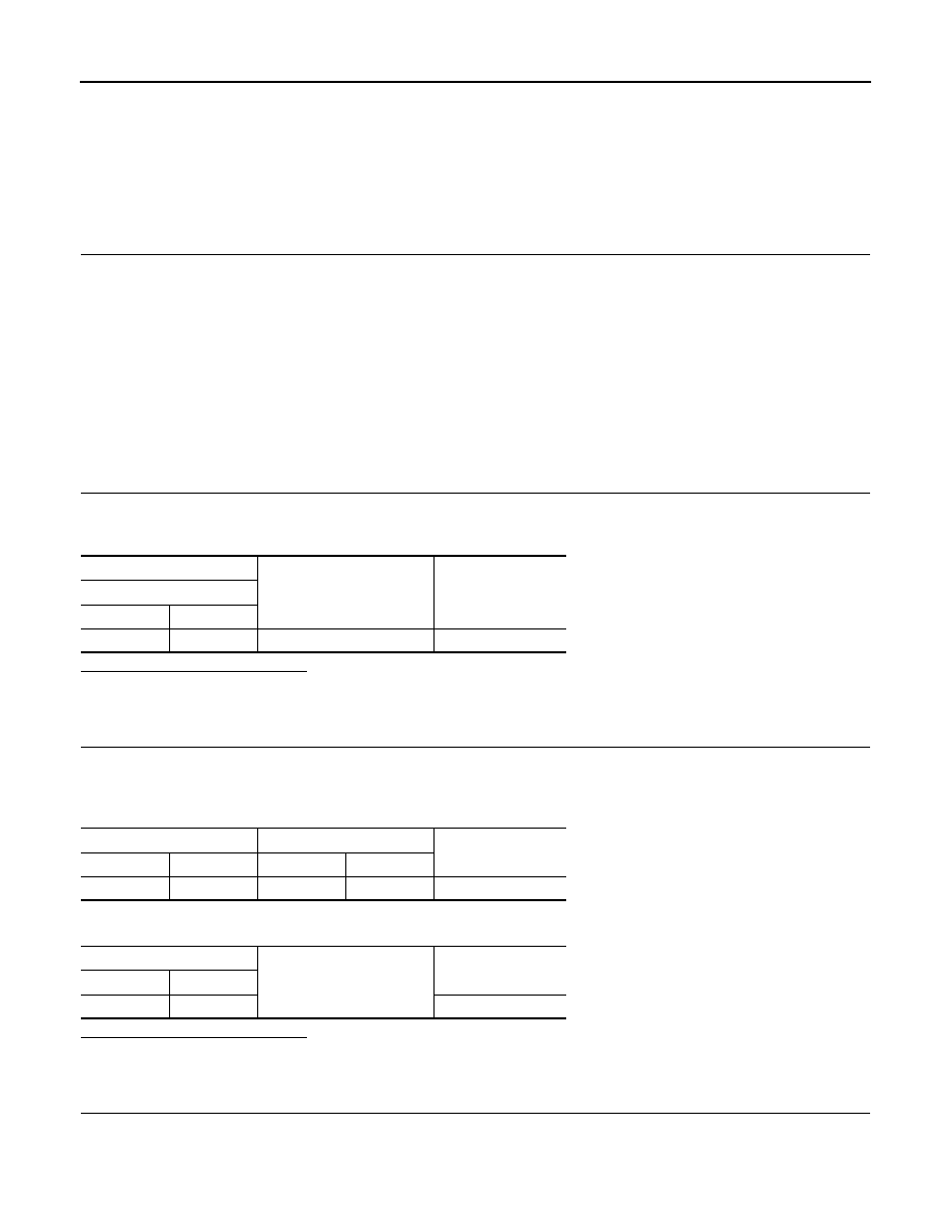
Test item
Condition
FRONT ON
: FRONT BUZZER ON
REAR ON
: REAR BUZZER ON
(+)
(
−
)
Voltage
(Approx.)
Buzzer
Connector
Terminal
B231
1
Ground
Battery voltage
Sonar control unit
Buzzer
Continuity
Connector
Terminal
Connector
Terminal
M44
23
B231
2
Existed
Sonar control unit
Ground
Continuity
Connector
Terminal
M44
23
Not existed
Нет комментариевНе стесняйтесь поделиться с нами вашим ценным мнением.
Текст