Infiniti EX35. Manual — part 202

AV
BUZZER CIRCUIT
AV-589
< COMPONENT DIAGNOSIS >
[BOSE AUDIO WITH NAVIGATION]
C
D
E
F
G
H
I
J
K
L
M
B
A
O
P
BUZZER CIRCUIT
Description
INFOID:0000000003597481
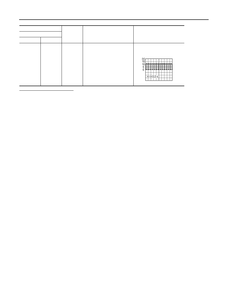
The sonar control unit outputs the buzzer signal when the rear sonar detects the obstacle.
Component Function Check
INFOID:0000000003597482
1.
SONAR CONTROL UNIT ACTIVE TEST
Check the buzzer operation with the sonar control unit active test.
BUZZER
>> INSPECTION END
Diagnosis Procedure
INFOID:0000000003597483
1.
CHECK BUZZER POWER SUPPLY
1.
Turn ignition switch ON.
2.
Check voltage between buzzer harness connector and ground.
Is the inspection result normal?
YES
>> GO TO 2.
NO
>> Repair harness or connector.
2.
CHECK HARNESS BUZZER SIGNAL CIRCUIT
1.
Turn ignition switch OFF.
2.
Disconnect sonar control unit connector and buzzer connector.
3.
Check continuity between sonar control unit harness connector and buzzer harness connector.
4.
Check continuity between sonar control unit harness connector and ground.
Is the inspection result normal?
YES
>> GO TO 3.
NO
>> Repair harness or connector.
3.
CHECK SIGNAL SONAR CONTROL UNIT
1.
Connect sonar control unit connector and buzzer connector.
2.
Check signal between sonar control unit harness connector and ground.
Test item
Condition
On
: Buzzer is operation.
Off
: Buzzer is not operation.
(+)
(
−
)
Voltage
(Approx.)
Buzzer
Connector
Terminal
B240
1
Ground
Battery voltage
Sonar control unit
Buzzer
Continuity
Connector
Terminal
Connector
Terminal
M47
23
B240
2
Existed
Sonar control unit
Ground
Continuity
Connector
Terminal
M47
23
Not existed
AV-590
< COMPONENT DIAGNOSIS >
[BOSE AUDIO WITH NAVIGATION]
BUZZER CIRCUIT
Is the inspection result normal?
YES
>> INSPECTION END
NO
>> Replace sonar control unit.
(+)
(
−
)
Condition
Signal
Sonar control unit
Connector
Terminal
M47
23
Ground
When buzzer operation
NOTE:
Waveform period changes due to
the distance to an obstacle.
SKIB8943E
AV
AV CONTROL UNIT
AV-591
< ECU DIAGNOSIS >
[BOSE AUDIO WITH NAVIGATION]
C
D
E
F
G
H
I
J
K
L
M
B
A
O
P
ECU DIAGNOSIS
AV CONTROL UNIT
Reference Value
INFOID:0000000003160740
VALUES ON THE DIAGNOSIS TOOL
CONSULT-III MONITOR ITEM
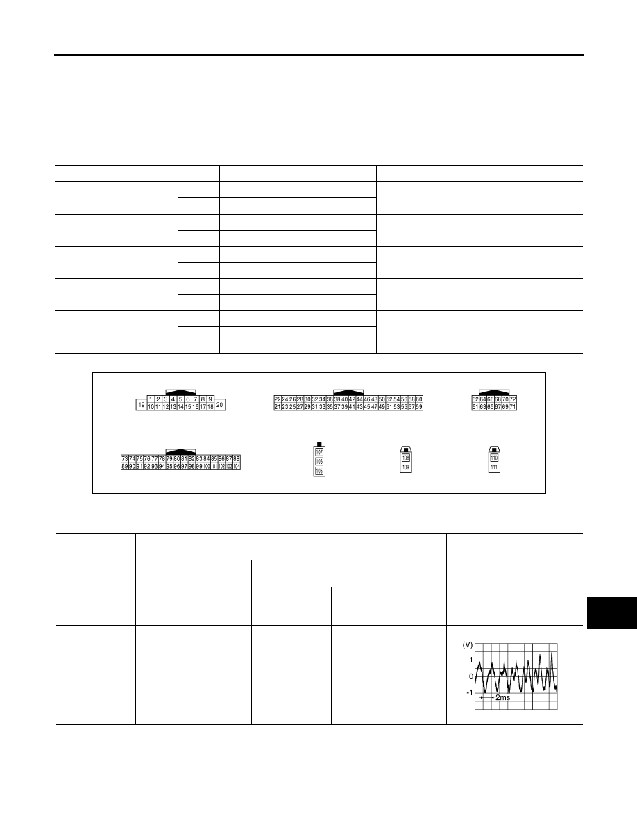
TERMINAL LAYOUT
PHYSICAL VALUES
Display Item
Display
Vehicle status
Remarks
VHCL SPD SIG
ON
Vehicle speed >0 km/h (0 MPH)
Changes in indication may be delayed. This is nor-
mal.
OFF
Vehicle speed =0 km/h (0 MPH)
PKB SIG
ON
Parking brake is applied.
Changes in indication may be delayed. This is nor-
mal.
OFF
Parking brake is released.
ILLUM SIG
ON
Light switch ON
—
OFF
Light switch OFF
IGN SIG
ON
Ignition switch ON
—
OFF
Ignition switch in ACC position
REV SIG
ON
Selector lever in R position
Changes in indication may be delayed. This is nor-
mal.
OFF
Selector lever in any position other
than R
JPNIA0004ZZ
Terminal
(Wire color)
Description
Condition
Reference value
(Approx.)
+
–
Signal name
Input/
Output
1
(V)
Ground
Amp. ON signal
Output
Ignition
switch
ON
—
12.0 V
2
(P)
3
(L)
Sound signal front LH
Output
Ignition
switch
ON
Audio output
SKIB3609E
AV-592
< ECU DIAGNOSIS >
[BOSE AUDIO WITH NAVIGATION]
AV CONTROL UNIT
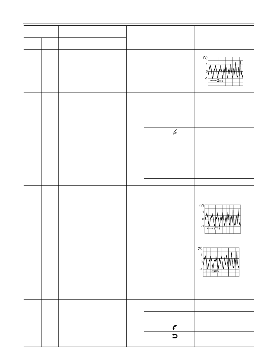
4
(V)
5
(SB)
Sound signal rear LH
Output
Ignition
switch
ON
Audio output
6
(P)
15
(B)
Steering switch signal A
Input
Ignition
switch
ON
Keep pressing SOURCE
switch.
0 V
Keep pressing MENU UP
switch.
1.0 V
Keep pressing MENU
DOWN switch.
2.0 V
Keep pressing
switch
3.0 V
Keep pressing ENTER
switch.
4.0 V
Except for above.
5.0 V
7
(V)
Ground
ACC power supply
Input
Ignition
switch
ACC
—
Battery voltage
9
(R)
Ground
Illumination signal
Input
OFF
Lighting switch is OFF.
0 V
Lighting switch is ON.
12.0 V
10
(B)
—
Shield
—
—
—
—
11
(R)
12
(G)
Sound signal front RH
Output
Ignition
switch
ON
Audio output
13
(BR)
14
(Y)
Sound signal rear RH
Output
Ignition
switch
ON
Audio output
15
(B)
Ground
Steering switch signal
ground
—
Ignition
switch
ON
—
0 V
16
(L)
15
(B)
Steering switch signal B
Input
Ignition
switch
ON
Keep pressing VOL DOWN
switch.
0 V
Keep pressing VOL UP
switch.
1.0 V
Keep pressing
switch.
2.0 V
Keep pressing
switch.
3.0 V
Except for above.
5.0 V
Terminal
(Wire color)
Description
Condition
Reference value
(Approx.)
+
–
Signal name
Input/
Output
SKIB3609E
SKIB3609E
SKIB3609E
Нет комментариевНе стесняйтесь поделиться с нами вашим ценным мнением.
Текст