Infiniti EX35. Manual — part 1092
MWI-46
< COMPONENT DIAGNOSIS >
B2201 COMMUNICATION ERROR 1
B2201 COMMUNICATION ERROR 1
Description
INFOID:0000000003140189
The communication line (LCD <-> AMP.) is used to communicate signals between the combination meter and
the unified meter and A/C amp. in order to control the information display.
DTC Logic
INFOID:0000000003140190
DTC DETECTION LOGIC
Diagnosis Procedure
INFOID:0000000003140191
1.
CHECK CONNECTOR
Check combination meter, unified meter and A/C amp. and terminals (combination meter side, unified meter
and A/C amp. side, and harness side) for looseness or bent.
Is the inspection result normal?
YES
>> GO TO 2.
NO
>> Repair terminal or connector.
2.
CHECK CONTINUITY COMMUNICATION CIRCUIT
1.
Turn ignition switch OFF.
2.
Disconnect combination meter connector and unified meter and A/C amp. connector.
3.
Check continuity between combination meter harness connector and unified meter and A/C amp. harness
connector.
4.
Check continuity between combination meter harness connector and ground.
Is the inspection result normal?
YES
>> GO TO 3.
NO
>> Repair harness or connector.
3.
CHECK UNIFIED METER AND A/C AMP. OUTPUT VOLTAGE
1.
Connect unified meter and A/C amp. connector.
2.
Turn ignition switch ON.
3.
Check voltage between unified meter and A/C amp. harness connector and ground.
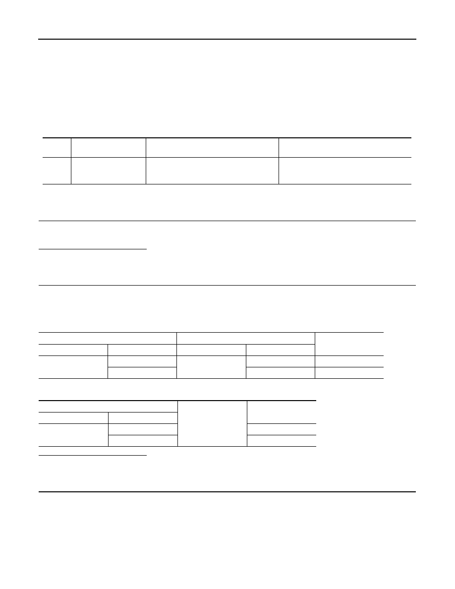
DTC
Display contents of
CONSULT-III
Diagnostic item is detected when ...
Probable malfunction location
B2201
COMM ERROR 1
If a communication error is present in the
communication line (LCD <-> AMP.) for 2 sec-
onds or more
Communication line (LCD <-> AMP.) circuit
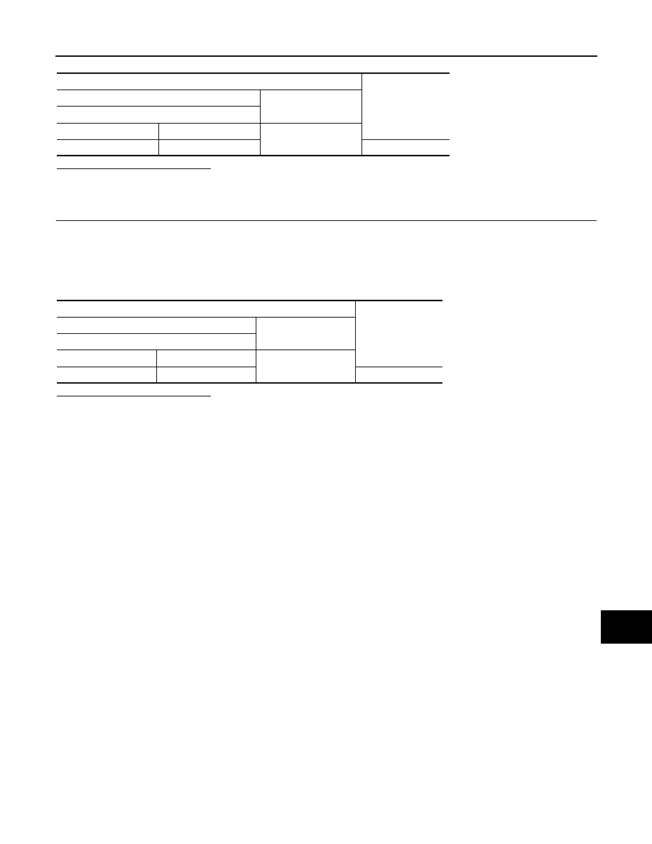
Combination meter
Unified meter and A/C amp.
Continuity
Connector
Terminal
Connector
Terminal
M53
24
M66
14
Existed
25
34
Existed
Combination meter
Ground
Continuity
Connector
Terminal
M53
24
Not existed
25
Not existed
MWI
B2201 COMMUNICATION ERROR 1
MWI-47
< COMPONENT DIAGNOSIS >
C
D
E
F
G
H
I
J
K
L
M
B
A
O
P
Is the inspection result normal?
YES
>> GO TO 4.
NO
>> Replace unified meter and A/C amp.
4.
CHECK COMBINATION METER OUTPUT VOLTAGE
1.
Turn ignition switch OFF.
2.
Disconnect unified meter and A/C amp. connector.
3.
Connect combination meter connector.
4.
Turn ignition switch ON.
5.
Check voltage between combination meter harness connector and ground.
Is the inspection result normal?
YES
>> INSPECTION END
NO
>> Replace combination meter.
Terminals
Voltage
(Approx.)
(+)
(-)
Unified meter A/C amp.
Connector
Terminal
Ground
M66
14
12 V
Terminal
Voltage
(Approx.)
(+)
(-)
Combination meter
Connector
Terminal
Ground
M53
25
5 V
MWI-48
< COMPONENT DIAGNOSIS >
B2202 COMMUNICATION ERROR 2
B2202 COMMUNICATION ERROR 2
Description
INFOID:0000000003140192
The communication line (METER <-> AMP.) is used to communicate signals between the combination meter
and the unified meter and A/C amp. in order to control the information display.
DTC Logic
INFOID:0000000003140193
DTC DETECTION LOGIC
Diagnosis Procedure
INFOID:0000000003140194
1.
CHECK CONNECTOR
Check combination meter, unified meter and A/C amp. and terminals (combination meter side, unified meter
and A/C amp. side, and harness side) for looseness or bent.
Is the inspection result normal?
YES
>> GO TO 2.
NO
>> Repair terminal or connector.
2.
CHECK CONTINUITY COMMUNICATION CIRCUIT
1.
Turn ignition switch OFF.
2.
Disconnect combination meter connector and unified meter and A/C amp. connector.
3.
Check continuity between combination meter harness connector and unified meter and A/C amp. harness
connector.
4.
Check continuity between combination meter harness connector and ground.
Is the inspection result normal?
YES
>> GO TO 3.
NO
>> Repair harness or connector.
3.
CHECK UNIFIED METER AND A/C AMP. OUTPUT VOLTAGE
1.
Turn ignition switch OFF.
2.
Disconnect combination meter connector.
3.
Connect unified meter and A/C amp. connector.
4.
Turn ignition switch ON.
5.
Check voltage between unified meter and A/C amp. harness connector and ground.
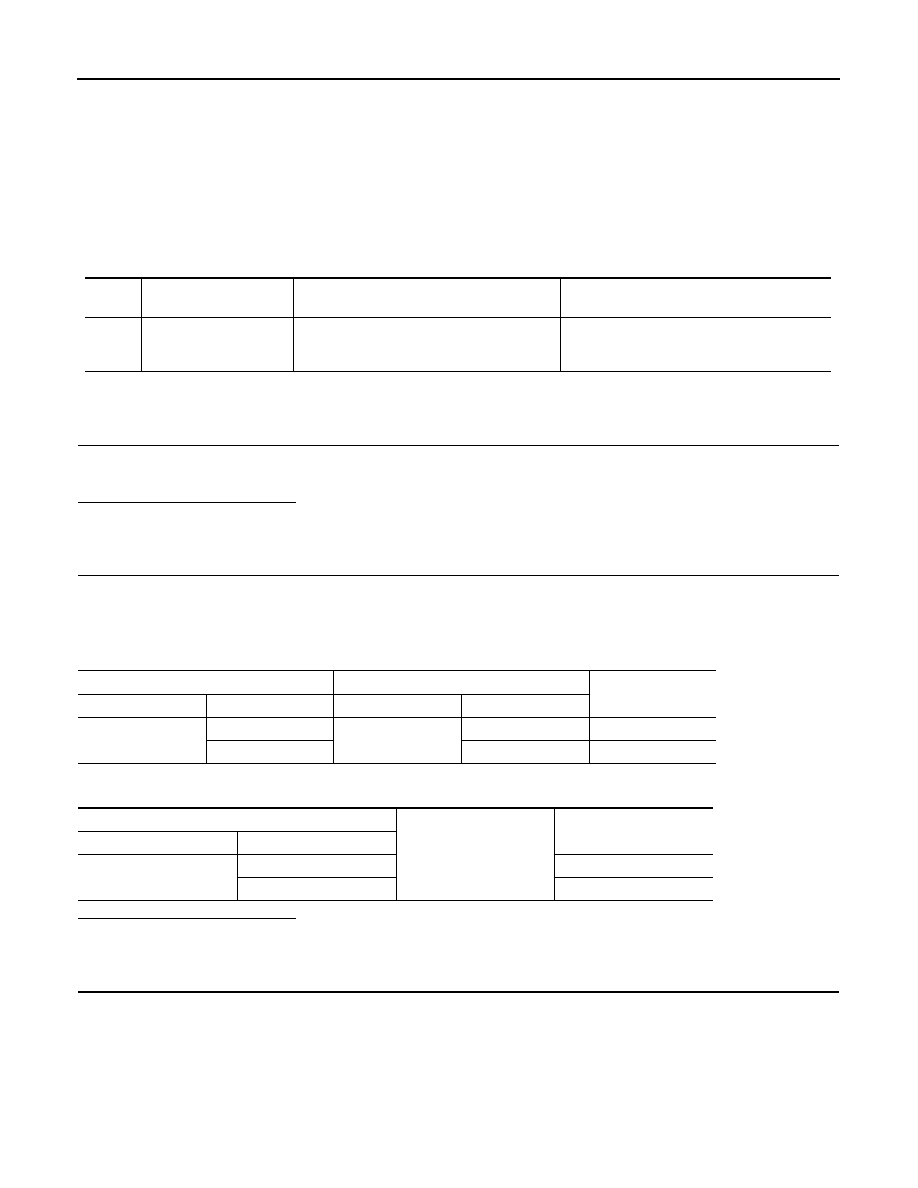
DTC
Display contents of
CONSULT-III
Diagnostic item is detected when ...
Probable malfunction location
B2202
COMM ERROR 2
If a communication error is present in the
communication line (METER <-> AMP.) for 2
seconds or more
Communication line (METER <-> AMP.) circuit
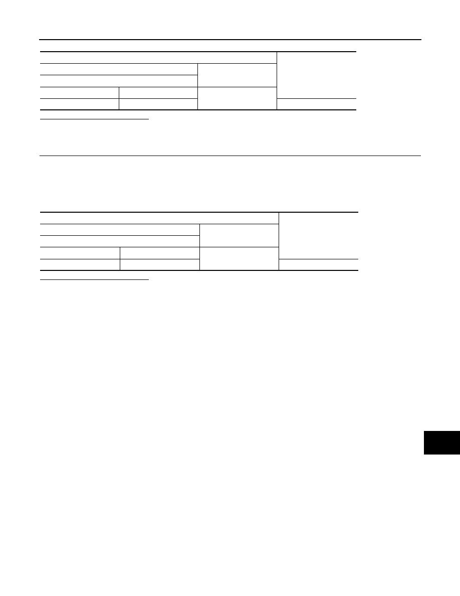
Combination meter
Unified meter and A/C amp.
Continuity
Connector
Terminal
Connector
Terminal
M53
2
M66
27
Existed
3
7
Existed
Combination meter
Ground
Continuity
Connector
Terminal
M53
2
Not existed
3
Not existed
MWI
B2202 COMMUNICATION ERROR 2
MWI-49
< COMPONENT DIAGNOSIS >
C
D
E
F
G
H
I
J
K
L
M
B
A
O
P
Is the inspection result normal?
YES
>> GO TO 4.
NO
>> Replace unified meter and A/C amp.
4.
CHECK COMBINATION METER OUTPUT VOLTAGE
1.
Turn ignition switch OFF.
2.
Disconnect unified meter and A/C amp. connector.
3.
Connect combination meter connector.
4.
Turn ignition switch ON.
5.
Check voltage between combination meter harness connector and ground.
Is the inspection result normal?
YES
>> INSPECTION END
NO
>> Replace combination meter.
Terminals
Voltage
(Approx.)
(+)
(-)
Unified meter A/C amp.
Connector
Terminal
Ground
M66
27
5 V
Terminals
Voltage
(Approx.)
(+)
(-)
Combination meter
Connector
Treminal
Ground
M53
3
5 V
Нет комментариевНе стесняйтесь поделиться с нами вашим ценным мнением.
Текст