Infiniti EX35. Manual — part 1045
LAN
AFS BRANCH LINE CIRCUIT
LAN-239
< COMPONENT DIAGNOSIS >
[CAN SYSTEM (TYPE 10)]
C
D
E
F
G
H
I
J
K
L
B
A
O
P
N
AFS BRANCH LINE CIRCUIT
Diagnosis Procedure
INFOID:0000000003515809
1.
CHECK CONNECTOR
1.
Turn the ignition switch OFF.
2.
Disconnect the battery cable from the negative terminal.
3.
Check the terminals and connectors of the AFS control unit for damage, bend and loose connection (unit
side and connector side).
Is the inspection result normal?
YES
>> GO TO 2.
NO
>> Repair the terminal and connector.
2.
CHECK HARNESS FOR OPEN CIRCUIT
1.
Disconnect the connector of AFS control unit.
2.
Check the resistance between the AFS control unit harness connector terminals.
Is the measurement value within the specification?
YES
>> GO TO 3.
NO
>> Repair the AFS control unit branch line.
3.
CHECK POWER SUPPLY AND GROUND CIRCUIT
Check the power supply and the ground circuit of the AFS control unit. Refer to
.
Is the inspection result normal?
YES (Present error)>>Replace the AFS control unit. Refer to
EXL-200, "Removal and Installation"
.
YES (Past error)>>Error was detected in the AFS control unit branch line.
NO
>> Repair the power supply and the ground circuit.
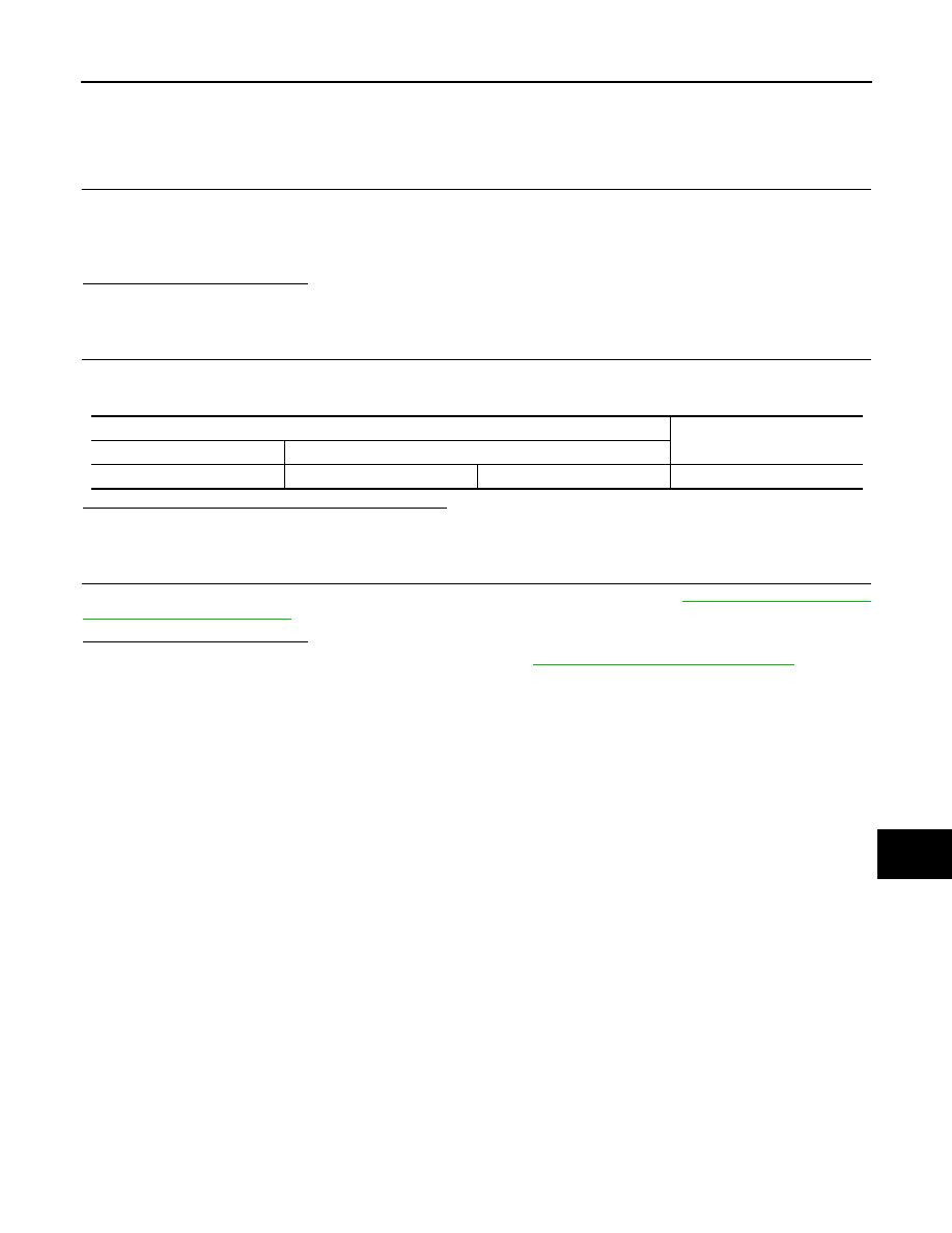
AFS control unit harness connector
Resistance (
Ω
)
Connector No.
Terminal No.
M16
30
7
Approx. 54 – 66

LAN-240
< COMPONENT DIAGNOSIS >
[CAN SYSTEM (TYPE 10)]
AV BRANCH LINE CIRCUIT
AV BRANCH LINE CIRCUIT
Diagnosis Procedure
INFOID:0000000003515810
1.
CHECK CONNECTOR
1.
Turn the ignition switch OFF.
2.
Disconnect the battery cable from the negative terminal.
3.
Check the terminals and connectors of the AV control unit for damage, bend and loose connection (unit
side and connector side).
Is the inspection result normal?
YES
>> GO TO 2.
NO
>> Repair the terminal and connector.
2.
CHECK HARNESS FOR OPEN CIRCUIT
1.
Disconnect the connector of AV control unit.
2.
Check the resistance between the AV control unit harness connector terminals.
-
Models with NAVI
-
Models without NAVI
Is the measurement value within the specification?
YES
>> GO TO 3.
NO
>> Repair the AV control unit branch line.
3.
CHECK POWER SUPPLY AND GROUND CIRCUIT
Check the power supply and the ground circuit of the AV control unit. Refer to the following.
• Base audio without navigation:
AV-51, "AV CONTROL UNIT : Diagnosis Procedure"
• BOSE audio without navigation:
AV-218, "AV CONTROL UNIT : Diagnosis Procedure"
• BOSE audio with navigation:
AV-544, "AV CONTROL UNIT : Diagnosis Procedure"
Is the inspection result normal?
YES (Present error)>>Replace the AV control unit. Refer to the following.
• Base audio without navigation:
AV-156, "Removal and Installation"
• BOSE audio without navigation:
AV-412, "Removal and Installation"
AV-903, "Removal and Installation"
YES (Past error)>>Error was detected in the AV control unit branch line.
NO
>> Repair the power supply and the ground circuit.
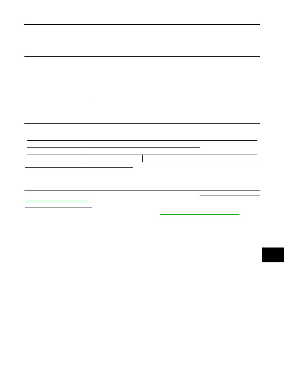
AV control unit harness connector
Resistance (
Ω
)
Connector No.
Terminal No.
M87
52
53
Approx. 54 – 66
AV control unit harness connector
Resistance (
Ω
)
Connector No.
Terminal No.
M85
86
87
Approx. 54 – 66
LAN
LANE BRANCH LINE CIRCUIT
LAN-241
< COMPONENT DIAGNOSIS >
[CAN SYSTEM (TYPE 10)]
C
D
E
F
G
H
I
J
K
L
B
A
O
P
N
LANE BRANCH LINE CIRCUIT
Diagnosis Procedure
INFOID:0000000003515811
1.
CHECK CONNECTOR
1.
Turn the ignition switch OFF.
2.
Disconnect the battery cable from the negative terminal.
3.
Check the following terminals and connectors for damage, bend and loose connection (unit side and con-
nector side).
-
Lane camera unit
-
Harness connector R7
-
Harness connector M110
Is the inspection result normal?
YES
>> GO TO 2.
NO
>> Repair the terminal and connector.
2.
CHECK HARNESS FOR OPEN CIRCUIT
1.
Disconnect the connector of lane camera unit.
2.
Check the resistance between the lane camera unit harness connector terminals.
Is the measurement value within the specification?
YES
>> GO TO 3.
NO
>> Repair the lane camera unit branch line.
3.
CHECK POWER SUPPLY AND GROUND CIRCUIT
Check the power supply and the ground circuit of the lane camera unit. Refer to
.
Is the inspection result normal?
YES (Present error)>>Replace the lane camera unit. Refer to
CCS-192, "Removal and Installation"
.
YES (Past error)>>Error was detected in the lane camera unit branch line.
NO
>> Repair the power supply and the ground circuit.
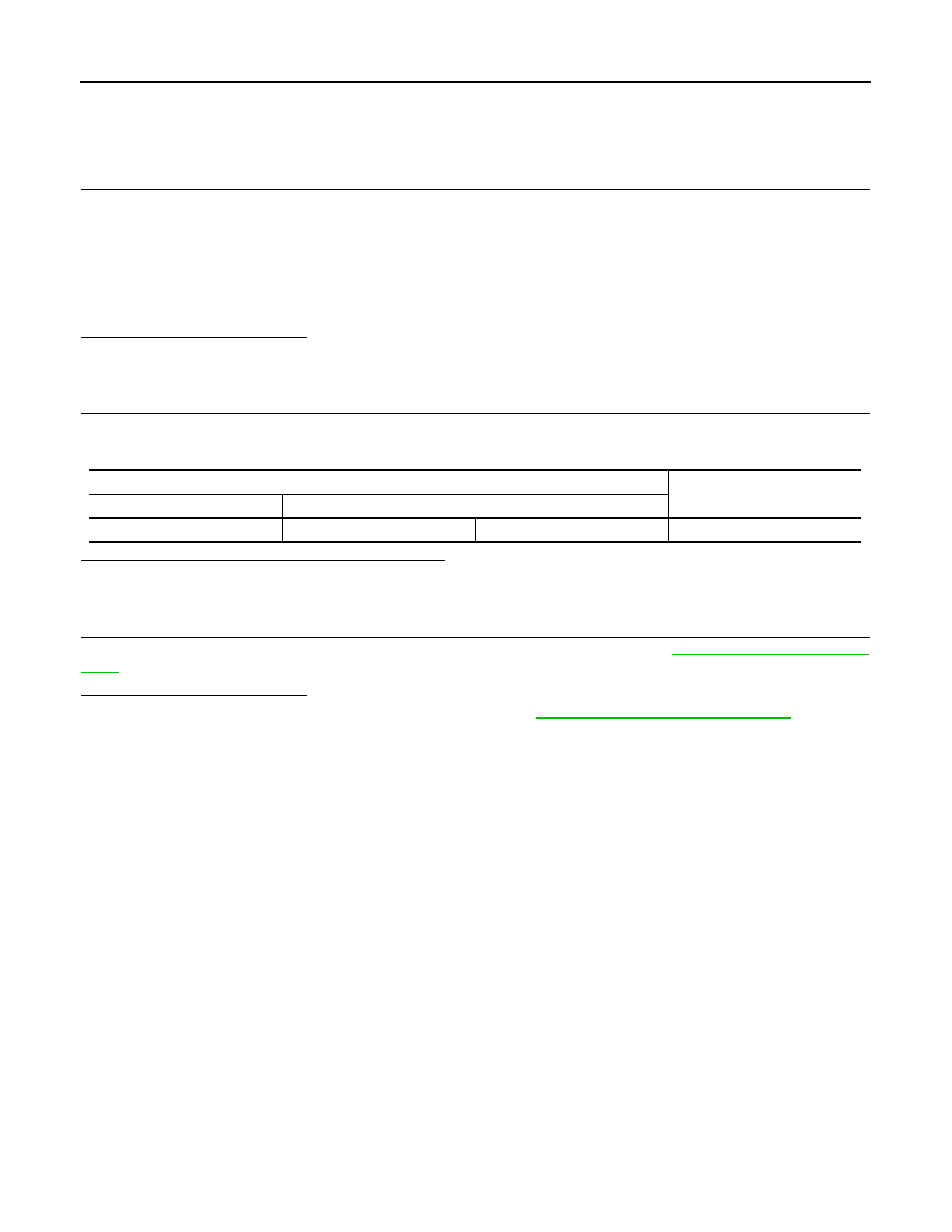
Lane camera unit harness connector
Resistance (
Ω
)
Connector No.
Terminal No.
R8
10
5
Approx. 54 – 66
LAN-242
< COMPONENT DIAGNOSIS >
[CAN SYSTEM (TYPE 10)]
4WD BRANCH LINE CIRCUIT
4WD BRANCH LINE CIRCUIT
Diagnosis Procedure
INFOID:0000000003515812
1.
CHECK CONNECTOR
1.
Turn the ignition switch OFF.
2.
Disconnect the battery cable from the negative terminal.
3.
Check the following terminals and connectors for damage, bend and loose connection (unit side and con-
nector side).
-
AWD control unit
-
Harness connector F103
-
Harness connector M116
Is the inspection result normal?
YES
>> GO TO 2.
NO
>> Repair the terminal and connector.
2.
CHECK HARNESS FOR OPEN CIRCUIT
1.
Disconnect the connector of AWD control unit.
2.
Check the resistance between the AWD control unit harness connector terminals.
Is the measurement value within the specification?
YES
>> GO TO 3.
NO
>> Repair the AWD control unit branch line.
3.
CHECK POWER SUPPLY AND GROUND CIRCUIT
Check the power supply and the ground circuit of the AWD control unit. Refer to
.
Is the inspection result normal?
YES (Present error)>>Replace the AWD control unit. Refer to
DLN-44, "Removal and Installation"
YES (Past error)>>Error was detected in the AWD control unit branch line.
NO
>> Repair the power supply and the ground circuit.
AWD control unit harness connector
Resistance (
Ω
)
Connector No.
Terminal No.
F108
8
16
Approx. 54 – 66
Нет комментариевНе стесняйтесь поделиться с нами вашим ценным мнением.
Текст