Infiniti EX35. Manual — part 74

AV
STEERING SWITCH SIGNAL B CIRCUIT
AV-77
< COMPONENT DIAGNOSIS >
[BASE AUDIO WITHOUT NAVIGATION]
C
D
E
F
G
H
I
J
K
L
M
B
A
O
P
Component Inspection
INFOID:0000000003562718
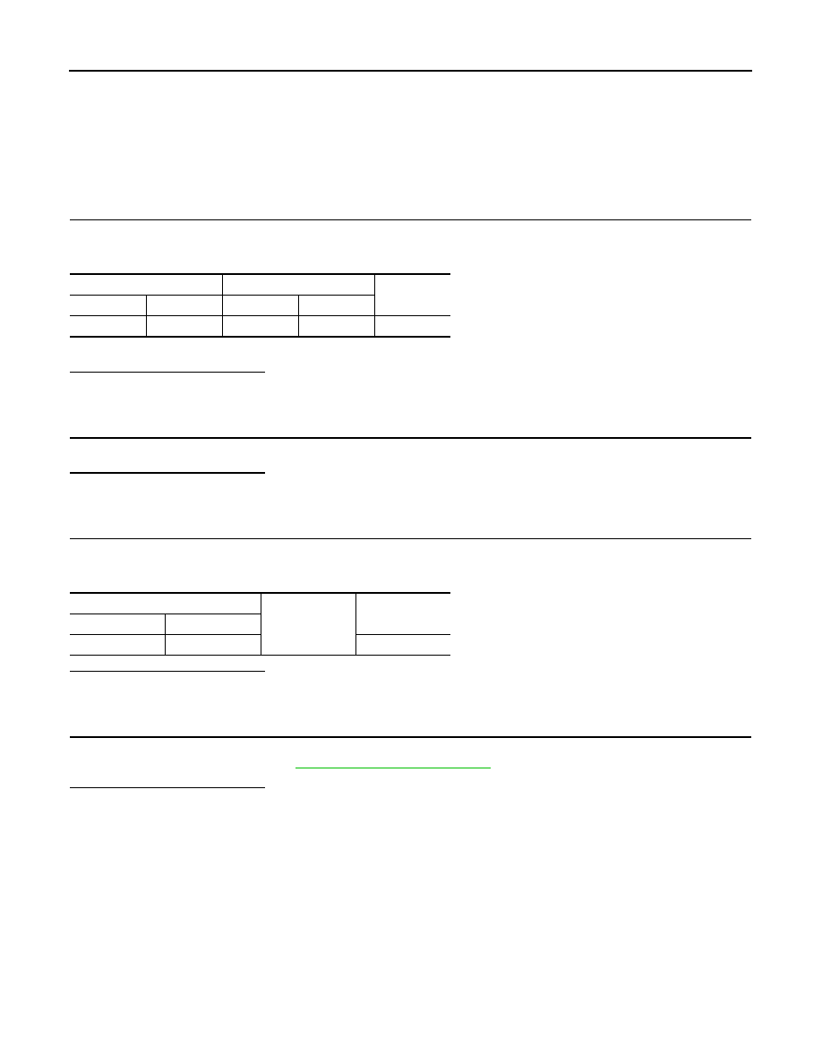
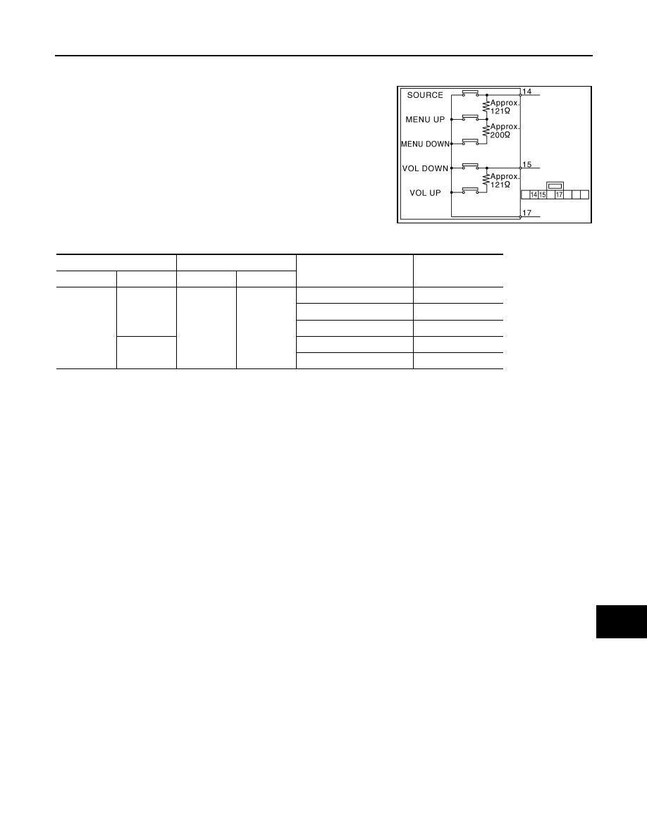
Measure the resistance between the steering switch connector.
JSNIA0215GB
Steering switch
Steering switch
Condition
Resistance value
(
Ω
)
Connector
Terminals
Connector
Terminal
M303
14
M303
17
SOURCE switch ON
0
MENU UP switch ON
120 – 122
MENU DOWN switch ON
318 – 324
15
VOL DOWN switch ON
0
VOL UP switch ON
120 – 122
AV-78
< COMPONENT DIAGNOSIS >
[BASE AUDIO WITHOUT NAVIGATION]
STEERING SWITCH SIGNAL GND CIRCUIT
STEERING SWITCH SIGNAL GND CIRCUIT
Description
INFOID:0000000003508424
Transmits the steering switch signal to AV control unit.
Diagnosis Procedure
INFOID:0000000003508425
1.
CHECK STEERING SWITCH SIGNAL GND CIRCUIT
1.
Disconnect AV control unit connector and spiral cable connector.
2.
Check continuity between AV control unit harness connector and spiral cable harness connector.
3.
Connect AV control unit connector.
Is the inspection result normal?
YES
>> GO TO 2.
NO
>> Repair harness or connector.
2.
CHECK SPIRAL CABLE
Check spiral cable.
Is the inspection result normal?
YES
>> GO TO 3.
NO
>> Replace spiral cable.
3.
CHECK GROUND CIRCUIT
1.
Connect AV control unit connector.
2.
Check continuity between AV control unit harness connector and ground.
Is the inspection result normal?
YES
>> GO TO 4.
NO
>> Replace AV control unit.
4.
CHECK STEERING SWITCH
1.
Turn ignition switch OFF.
2.
Check steering switch. Refer to
.
Is the inspection result normal?
YES
>> INSPECTION END
NO
>> Replace steering switch.
AV control unit
Spiral cable
Continuity
Connector
Terminal
Connector
Terminal
M81
15
M36
33
Existed
AV control unit
Ground
Continuity
Connector
Terminal
M81
15
Not existed
AV
STEERING SWITCH SIGNAL GND CIRCUIT
AV-79
< COMPONENT DIAGNOSIS >
[BASE AUDIO WITHOUT NAVIGATION]
C
D
E
F
G
H
I
J
K
L
M
B
A
O
P
Component Inspection
INFOID:0000000003562719
Measure the resistance between the steering switch connector.
JSNIA0215GB
Steering switch
Steering switch
Condition
Resistance value
(
Ω
)
Connector
Terminals
Connector
Terminal
M303
14
M303
17
SOURCE switch ON
0
MENU UP switch ON
120 – 122
MENU DOWN switch ON
318 – 324
15
VOL DOWN switch ON
0
VOL UP switch ON
120 – 122
AV-80
< ECU DIAGNOSIS >
[BASE AUDIO WITHOUT NAVIGATION]
AV CONTROL UNIT
ECU DIAGNOSIS
AV CONTROL UNIT
Reference Value
INFOID:0000000003508427
VALUES ON THE DIAGNOSIS TOOL
CONSULT-III MONITOR ITEM
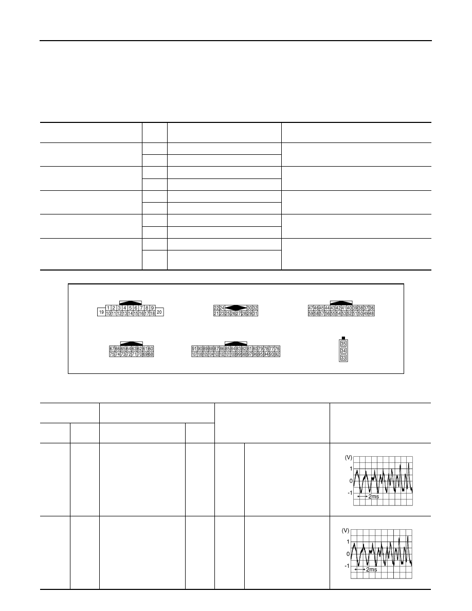
TERMINAL LAYOUT
PHYSICAL VALUES
Display Item
Dis-
play
Vehicle status
Remarks
VHCL SPD SIG
On
Vehicle speed >0 km/h (0 MPH)
Changes in indication may be delayed. This is nor-
mal.
Off
Vehicle speed =0 km/h (0 MPH)
PKB SIG
On
Parking brake is applied.
Changes in indication may be delayed. This is nor-
mal.
Off
Parking brake is released.
ILLUM SIG
On
Light switch ON
—
Off
Light switch OFF
IGN SIG
On
Ignition switch ON
—
Off
Ignition switch in ACC position
REV SIG
On
Shift the selector lever to “R” position
Changes in indication may be delayed. This is nor-
mal.
Off
Shift the selector lever other than “R”
position
JPNIA0012ZZ
Terminal
(Wire color)
Description
Condition
Reference value
(Approx.)
+
–
Signal name
Input/
Output
2
(L)
3
(W)
Sound signal front door
speaker LH and front tweet-
er LH
Output
Ignition
switch
ON
Audio output
4
(LG)
5
(L)
Sound signal rear door
speaker LH
Output
Ignition
switch
ON
Audio output
SKIB3609E
SKIB3609E
Нет комментариевНе стесняйтесь поделиться с нами вашим ценным мнением.
Текст