Infiniti EX35. Manual — part 885
GW-26
< ON-VEHICLE REPAIR >
REAR REGULATOR
REAR REGULATOR
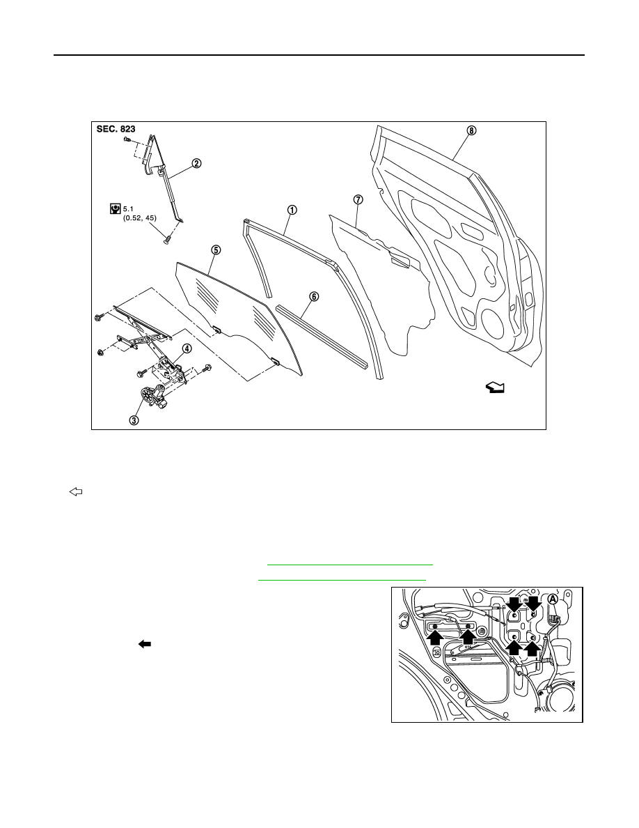
Exploded View
INFOID:0000000003744111
Removal and Installation
INFOID:0000000003566741
REMOVAL
1.
Remove the rear door finisher. Refer to
INT-17, "Removal and Installation"
.
2.
Remove the rear door glass. Refer to
GW-23, "Removal and Installation"
3.
Remove the regulator mounting bolts, disconnect the power win-
dow motor harness connector (A) and then remove the regulator
from the door panel.
4.
Remove the rear door glass run.
INSTALLATION
Install in the reverse order of removal.
1.
Rear door glass run
2.
Corner piece assembly
3.
Power window motor
4.
Regulator assembly
5.
Rear door glass
6.
Rear door inside seal
7.
Sealing screen
8.
Rear door panel
: Vehicle front
JMKIA1950GB
: Bolt
JMKIA1790ZZ

REAR REGULATOR
GW-27
< ON-VEHICLE REPAIR >
C
D
E
F
G
H
I
J
L
M
A
B
GW
N
O
P
Disassembly and Assembly
INFOID:0000000003566742
DISASSEMBLY
Remove power window motor from regulator assembly.
ASSEMBLY
Assemble in the reverse order of disassembly.
Inspection and Adjustment
INFOID:0000000003566743
Inspection after Removal
Check the regulator assembly for the following items. Replace or grease it if a malfunction is detected.
• Wire wear
• Regulator deformation
The arrows in the figure show the application points of the multi-purpose grease.
FITTING INSPECTION
• Check that the glass is fit securely into the sash groove.
• Lower the glass slightly [approximately 10 to 20 mm (0.394 to 0.787 in)], and check that the clearance to the
sash is parallel. Loosen the regulator mounting bolts, guide rail mounting bolts, and glass and carrier plate
mounting bolts to correct the glass position if the clearance between the glass and sash is not parallel.
: Grease application point
JMKIA1791ZZ
HA-1
VENTILATION, HEATER & AIR CONDITIONER
C
D
E
F
G
H
J
K
L
M
SECTION
HA
A
B
HA
N
O
P
CONTENTS
HEATER & AIR CONDITIONING SYSTEM
BASIC INSPECTION . . . . . . . . .
DIAGNOSIS AND REPAIR WORKFLOW . . ..
Work Flow . . . . . . . . . . . . . . . .....
FUNCTION DIAGNOSIS . . . . . . . ...
REFRIGERATION SYSTEM . . . . . . . ...
System Diagram . . . . . . . . . . . . . ....
System Description . . . . . . . . . . . . ...
Component Parts Location . . . . . . . . . ....
Component Description . . . . . . . . . . .....
SYMPTOM DIAGNOSIS . . . . . . . ...
REFRIGERATION SYSTEM SYMPTOMS . . ..
Trouble Diagnosis For Unusual Pressure . . . .....
Symptom Table . . . . . . . . . . . . . .....
PRECAUTION . . . . . . . . . . . ..
PRECAUTIONS . . . . . . . . . . . . ..
Precaution Necessary for Steering Wheel Rota-
tion after Battery Disconnect . . . . . . . . ...
Precaution for Procedure without Cowl Top Cover
Precautions For Xenon Headlamp Service . . . .
Working with HFC-134a (R-134a) . . . . . . ...
General Refrigerant Precaution . . . . . . . ..
Refrigerant Connection . . . . . . . . . . ...
Service Equipment . . . . . . . . . . . . ..
COMPRESSOR . . . . . . . . . . . . ..
General Precautions . . . . . . . . . . . ...
LEAK DETECTION DYE . . . . . . . . .
General Precautions . . . . . . . . . . . ...
PREPARATION . . . . . . . . . . ...
PREPARATION . . . . . . . . . . . . ..
Special Service Tool . . . . . . . . . . . .
Commercial Service Tool . . . . . . . . . .
Sealant or/and Lubricant . . . . . . . . . . .
ON-VEHICLE MAINTENANCE . . . . .
REFRIGERANT . . . . . . . . . . . . .
Collection and Charge . . . . . . . . . . . .
LUBRICANT . . . . . . . . . . . . . ..
Maintenance of Lubricant Quantity . . . . . . ..
Lubricant Adjusting Procedure for Components
Replacement Except Compressor . . . . . . ...
Lubricant Adjusting Procedure for Compressor
Replacement . . . . . . . . . . . . . . ...
REFRIGERATION SYSTEM . . . . . . . .
Inspection . . . . . . . . . . . . . . . .
Performance Chart . . . . . . . . . . . . ..
Refrigerant Leakages . . . . . . . . . . . ..
FLUORESCENT LEAK DETECTOR . . . .
Inspection . . . . . . . . . . . . . . . .
ELECTRICAL LEAK DETECTOR . . . . .
Inspection . . . . . . . . . . . . . . . .
ON-VEHICLE REPAIR . . . . . . . . .
COMPRESSOR . . . . . . . . . . . . .
Exploded View . . . . . . . . . . . . . . .
Removal and Installation . . . . . . . . . . .
Inspection . . . . . . . . . . . . . . . .
LOW-PRESSURE FLEXIBLE HOSE . . . .
Exploded View . . . . . . . . . . . . . . .
Removal and Installation . . . . . . . . . . .
HIGH-PRESSURE FLEXIBLE HOSE . . . ...
Exploded View . . . . . . . . . . . . . . .
Removal and Installation . . . . . . . . . . .
HA-2
Exploded View . . . . . . . . . . . . . ....
Removal and Installation . . . . . . . . . ....
LOW-PRESSURE PIPE 2 . . . . . . . . ..
Exploded View . . . . . . . . . . . . . ....
Removal and Installation . . . . . . . . . ....
LOW-PRESSURE PIPE 1 AND HIGH-PRES-
SURE PIPE 2 . . . . . . . . . . . . . .
Exploded View . . . . . . . . . . . . . ....
Removal and Installation . . . . . . . . . ....
CONDENSER . . . . . . . . . . . . .
Exploded View . . . . . . . . . . . . . ....
Removal and Installation . . . . . . . . . ....
CONDENSER PIPE ASSEMBLY . . . . . ..
Exploded View . . . . . . . . . . . . . ....
Removal and Installation . . . . . . . . . ....
LIQUID TANK . . . . . . . . . . . . .
Exploded View . . . . . . . . . . . . . ....
Removal and Installation . . . . . . . . . ....
REFRIGERANT PRESSURE SENSOR . . .
Exploded View . . . . . . . . . . . . . .
Removal and Installation . . . . . . . . . . .
EVAPORATOR . . . . . . . . . . . . ..
Exploded View . . . . . . . . . . . . . .
Removal and Installation . . . . . . . . . . .
EXPANSION VALVE . . . . . . . . . . .
Exploded View . . . . . . . . . . . . . .
Removal and Installation . . . . . . . . . . .
SERVICE DATA AND SPECIFICATIONS
(SDS) . . . . . . . . . . . . . . ..
SERVICE DATA AND SPECIFICATIONS
(SDS) . . . . . . . . . . . . . . . . .
Compressor . . . . . . . . . . . . . . .
Lubricant . . . . . . . . . . . . . . . . .
Refrigerant . . . . . . . . . . . . . . . ..
Engine Idling Speed . . . . . . . . . . . .
Нет комментариевНе стесняйтесь поделиться с нами вашим ценным мнением.
Текст