Infiniti EX35. Manual — part 70
AV
VERTICAL SYNCHRONIZING (VP) SIGNAL CIRCUIT
AV-61
< COMPONENT DIAGNOSIS >
[BASE AUDIO WITHOUT NAVIGATION]
C
D
E
F
G
H
I
J
K
L
M
B
A
O
P
VERTICAL SYNCHRONIZING (VP) SIGNAL CIRCUIT
Description
INFOID:0000000003508408
In composite image (AUX image, camera image), transmit the vertical synchronizing (VP) signal and horizon-
tal synchronizing (HP) signal from display unit to AV control unit so as to synchronize the RGB images dis-
played with AV control unit such as the image quality adjusting menu, etc.
Diagnosis Procedure
INFOID:0000000003508409
1.
CHECK CONTINUITY VERTICAL SYNCHRONIZING (VP) SIGNAL CIRCUIT
1.
Turn ignition switch OFF.
2.
Disconnect display unit connector and AV control unit connector.
3.
Check continuity between display unit harness connector and AV control unit harness connector.
4.
Check continuity between display unit harness connector and ground.
Is the inspection result normal?
YES
>> GO TO 2.
NO
>> Repair harness or connector.
2.
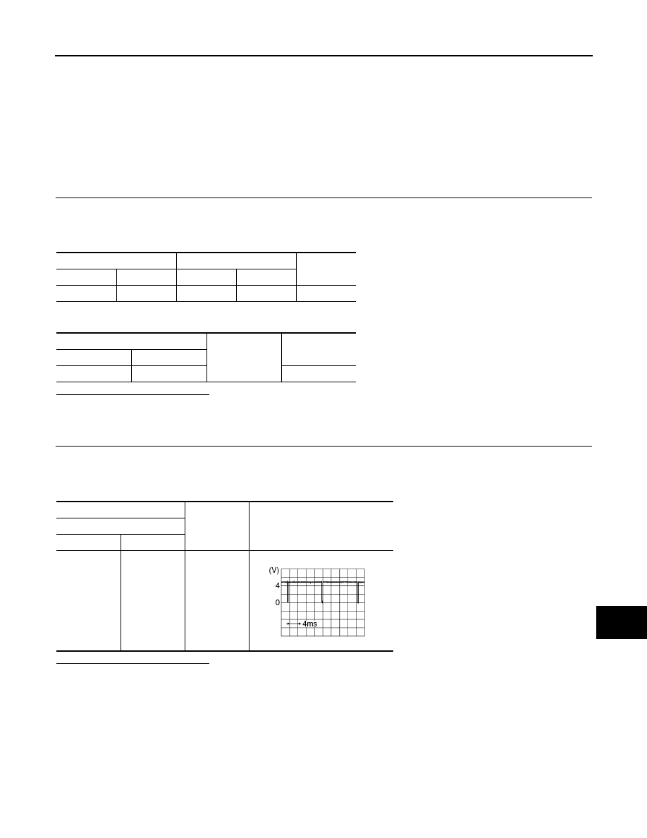
CHECK VERTICAL SYNCHRONIZING (VP) SIGNAL
1.
Connect display unit connector and AV control unit connector.
2.
Turn ignition switch ON.
3.
Check signal between display unit harness connector and ground.
Is the inspection result normal?
YES
>> Replace AV control unit.
NO
>> Replace display unit.
Display unit
AV control unit
Continuity
Connector
Terminal
Connector
Terminal
M71
20
M83
57
Existed
Display unit
Ground
Continuity
Connector
Terminal
M71
20
Not existed
(+)
(
−
)
Reference value
Display unit
Connector
Terminal
M71
20
Ground
SKIB3598E
AV-62
< COMPONENT DIAGNOSIS >
[BASE AUDIO WITHOUT NAVIGATION]
AUX IMAGE SIGNAL CIRCUIT
AUX IMAGE SIGNAL CIRCUIT
Description
INFOID:0000000003508410
• Transmits the image signal of AUX device from auxiliary input jacks to AV control unit.
• AV control unit transmits the image signal that is inputted to the display unit.
Diagnosis Procedure
INFOID:0000000003508411
1.
CHECK CONTINUITY AUX IMAGE SIGNAL CIRCUIT (AUX INPUT JACKS AND AV CONTROL UNIT)
1.
Turn ignition switch OFF.
2.
Disconnect auxiliary input jacks connector and AV control unit connector.
3.
Check continuity between auxiliary input jacks harness connector and AV control unit harness connector.
4.
Check continuity between auxiliary input jacks harness connector and ground.
Is the inspection result normal?
YES
>> GO TO 2.
NO
>> Repair harness or connector.
2.
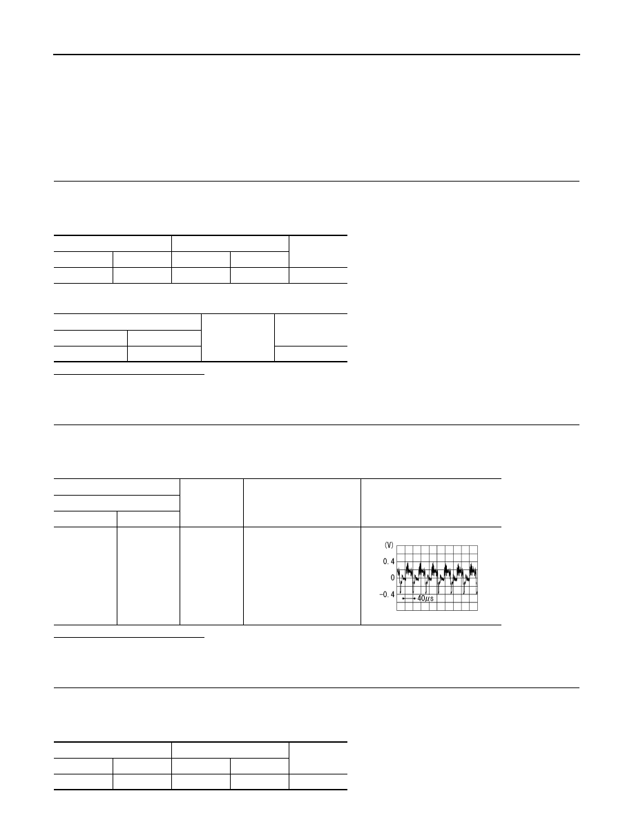
CHECK AUX IMAGE SIGNAL (AUX INPUT JACKS TO AV CONTROL UNIT)
1.
Connect display unit connector and AV control unit connector.
2.
Turn ignition switch ON.
3.
Check signal between auxiliary input jacks harness connector and ground.
Is the inspection result normal?
YES
>> GO TO 3.
NO
>> Check that there is no malfunction in the external device.
3.
CHECK CONTINUITY COMPOSITE IMAGE SIGNAL CIRCUIT (AV CONTROL UNIT AND DISPLAY UNIT)
1.
Turn ignition switch OFF.
2.
Disconnect auxiliary input jacks connector and AV control unit connector.
3.
Check continuity between display unit harness connector and AV control unit harness connector.
Auxiliary input jacks
AV control unit
Continuity
Connector
Terminal
Connector
Terminal
M154
7
M84
66
Existed
Auxiliary input jacks
Ground
Continuity
Connector
Terminal
M154
7
Not existed
(+)
(
−
)
Condition
Reference value
Auxiliary input jacks
Connector
Terminal
M154
7
Ground
At AUX image is displayed.
SKIB2251J
Display unit
AV control unit
Continuity
Connector
Terminal
Connector
Terminal
M71
15
M83
36
Existed
AV
AUX IMAGE SIGNAL CIRCUIT
AV-63
< COMPONENT DIAGNOSIS >
[BASE AUDIO WITHOUT NAVIGATION]
C
D
E
F
G
H
I
J
K
L
M
B
A
O
P
4.
Check continuity between display unit harness connector and ground.
Is the inspection result normal?
YES
>> GO TO 4.
NO
>> Repair harness or connector.
4.
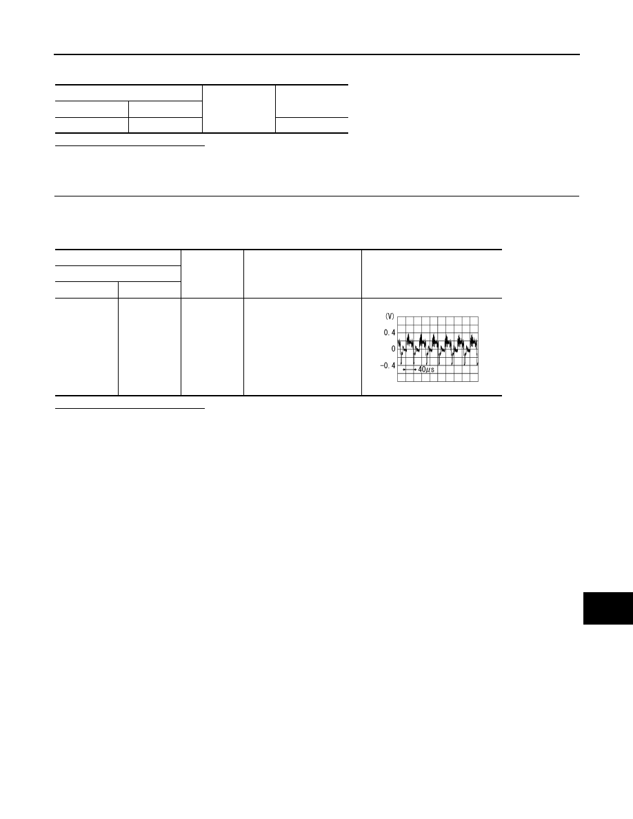
CHECK COMPOSITE IMAGE SIGNAL
1.
Connect AV control unit connector and display unit connector.
2.
Turn ignition switch ON.
3.
Check signal between display unit harness connector and ground.
Is the inspection result normal?
YES
>> Replace display unit.
NO
>> Replace AV control unit.
Display unit
Ground
Continuity
Connector
Terminal
M71
15
Not existed
(+)
(
−
)
Condition
Reference value
Display unit
Connector
Terminal
M71
15
Ground
At AUX image is displayed.
SKIB2251J
AV-64
< COMPONENT DIAGNOSIS >
[BASE AUDIO WITHOUT NAVIGATION]
DISK EJECT SIGNAL CIRCUIT
DISK EJECT SIGNAL CIRCUIT
Description
INFOID:0000000003508412
The disk eject signal is output to AV control unit when the eject switch of multifunction switch is pressed.
Diagnosis Procedure
INFOID:0000000003508413
1.
CHECK CONTINUITY DISK EJECT SIGNAL CIRCUIT
1.
Turn ignition switch OFF.
2.
Disconnect multifunction switch connector and AV control unit connector.
3.
Check continuity between multifunction switch harness connector and AV control unit harness connector.
4.
Check continuity between multifunction switch harness connector and ground.
Is the inspection result normal?
YES
>> GO TO 2.
NO
>> Repair harness or connector.
2.
CHECK AV CONTROL UNIT VOLTAGE
1.
Connect AV control unit connector.
2.
Turn ignition switch ON.
3.
Check voltage between AV control unit harness connector and ground.
Is the inspection result normal?
YES
>> Replace preset switch.
NO
>> Replace AV control unit.
Multifunction switch
AV control unit
Continuity
Connector
Terminal
Connector
Terminal
M72
14
M85
103
Existed
Multifunction switch
Ground
Continuity
Connector
Terminal
M72
14
Not existed
(+)
(
−
)
Reference value
(Approx.)
AV control unit
Connector
Terminal
M85
103
Ground
3.3 V
Нет комментариевНе стесняйтесь поделиться с нами вашим ценным мнением.
Текст