Infiniti EX35. Manual — part 181
AV
DIAGNOSIS SYSTEM (AROUND VIEW MONITOR CONTROL UNIT)
AV-505
< FUNCTION DIAGNOSIS >
[BOSE AUDIO WITH NAVIGATION]
C
D
E
F
G
H
I
J
K
L
M
B
A
O
P
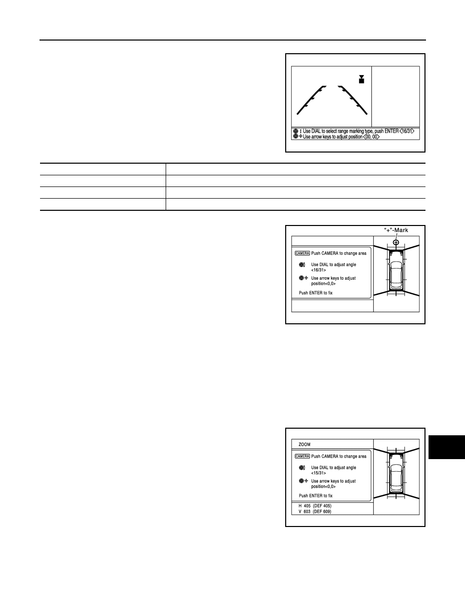
Correct Draw Line of Camera Image
The display position of guiding lines when displayed on the rear
view, front view, and front-side view can be changed.
Correct Draw Line of Camera Image item
Fine Tuning of Birds-Eye View
• The fine adjustment function of camera calibration can check and
adjust the difference between each camera.
• Fine adjustments can be performed for each camera. Move the
“+”-mark to select the camera by pressing the “CAMERA” switch.
• Perform the adjustment with the center dial and upper/lower/left/
right switches.
CAUTION:
Operate the center dial slowly because the changing of the
screen takes approximately 1 second.
NOTE:
• It can be initialized to the NISSAN factory shipment setting with
“Initialize Camera Image Calibration” of “Calibrating Camera
Image”.
• The adjustment value is cancelled in this mode by performing “Initialize Camera Image Calibration”.
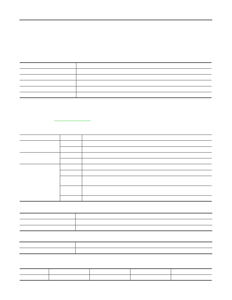
ZOOM function
• The ZOOM ratio of camera can be changed when calibrating the
camera.
• It shifts to ZOOM function mode by shifting the selector lever to a
position other than the “R” position
→
“R” position
→
other than “R”
position in the “Fine Tuning of Birds-Eye View” mode.
• The changing of ZOOM ratio can be performed for each camera.
Move the “+”-mark to select the camera by pressing “CAMERA”
switch and press the left/right switch to change the ZOOM ratio.
NOTE:
• When the position is not correct in “Fine Tuning of Birds-Eye View”
mode, use this "ZOOM" function to adjust it.
• If this function is used, always adjust the upper/lower/left/right posi-
tion again on the “Fine Tuning of Birds-Eye View” screen.
Adjustment range
Rotating direction
: 31 patterns
Upper/lower direction
:
−
25 – 25
Left/right direction
:
−
25 – 25
JSNIA1058GB
Items
Description
Rear View
The position of rear view guiding line can be changed.
Front-Side View
The position of Front-Side view guiding line can be changed.
Front View
The position of Front view guiding line can be changed.
Adjustment range
Rotating direction
: 31 patterns (16 on the
center)
Upper/lower direction
:
−
99 – 99
Left/right direction
:
−
99
−
99
JSNIA1055GB
JSNIA1059GB
AV-506
< FUNCTION DIAGNOSIS >
[BOSE AUDIO WITH NAVIGATION]
DIAGNOSIS SYSTEM [SONAR CONTROL UNIT (WITH AROUND VIEW MONI-
TOR)]
DIAGNOSIS SYSTEM [SONAR CONTROL UNIT (WITH AROUND VIEW
MONITOR)]
CONSULT-III Function (SONAR)
INFOID:0000000003160631
DESCRIPTION
CONSULT-III can display each diagnostic item using the diagnostic test modes shown as follows:
ECU IDENTIFICATION
Displays the part number of sonar control unit.
SELF-DIAGNOSTIC RESULTS
For details, refer to
.
DATA MONITOR
ACTIVE TEST
WORK SUPPORT
CORNER SEN DISTANCE SET
Corner sensor warning buzzer distance can be set to 4 phases as follows.
Test mode
Function
Ecu Identification
Sonar control unit part number can be read.
Self Diagnostic Result
Sonar control unit checks the conditions and displays memorized error.
Data monitor
Sonar control unit input/output data in real time.
Active Test
Gives a drive signal to a load to check the operation.
Work support
Changes setting of each function.
Monitor Item
Display
Description
SONAR OPE
On
Around view monitor is ON. (sonar system is ON)
Off
Around view monitor is OFF. (sonar system is OFF)
BUZZER OUTPUT
On
Buzzer is output condition.
Off
Buzzer is not output condition.
CR SEN [FL]
CR SEN [FR]
CR SEN [RL]
CR SEN [RR]
ERROR
When a sensor is abnormal.
LV.0
When a sensor is not detection.
LV.2
The distance between the corner sensor and an obstacle is 60 cm (23.6 in) or more and
less then 70 cm (27.5 in).
LV.3
The distance between the corner sensor and an obstacle is 40 cm (15.7 in) or more and
less then 60 cm (23.6 in).
LV.4
The distance between corner sensor and an obstacle less than 40 cm (15.7 in).
Active test item
Function
BUZZER
This test is able to check buzzer (forward/backward) operation.
SONAR SENSOR
This test is able to check each sonar sensor operation.
Work support item
Function
CORNER SEN DISTANCE SET
Corner sensor warning buzzer distance is adjustable to 4 phases.
Warning item
FARTHER
FAR
NORMAL
NEAR
Second warning
70 – 80 cm (27.5 – 31.4 in)
60 – 70 cm (23.6 – 27.5 in)
50 – 60 cm (19.6 – 23.6 in)
40 – 50 cm (15.7 – 19.6 in)

AV
DIAGNOSIS SYSTEM [SONAR CONTROL UNIT (WITH AROUND VIEW MONI-
TOR)]
AV-507
< FUNCTION DIAGNOSIS >
[BOSE AUDIO WITH NAVIGATION]
C
D
E
F
G
H
I
J
K
L
M
B
A
O
P
The default of this model is “FAR”.
Third warning
50 – 70 cm (19.6 – 27.5 in)
40 – 60 cm (15.7 – 23.6 in)
30 – 50 cm (11.8 – 19.6 in)
30 – 40 cm (11.8 – 15.7 in)
Fourth warning
Less than 50 cm (19.6 in)
Less than 40 cm (15.7 in)
Less than 30 cm (11.8 in)
Less than 30 cm (11.8 in)
Warning item
FARTHER
FAR
NORMAL
NEAR

AV-508
< COMPONENT DIAGNOSIS >
[BOSE AUDIO WITH NAVIGATION]
U1000 CAN COMM CIRCUIT
COMPONENT DIAGNOSIS
U1000 CAN COMM CIRCUIT
Description
INFOID:0000000003160632
CAN (Controller Area Network) is a serial communication line for real time application. It is an on-vehicle mul-
tiplex communication line with high data communication speed and excellent error detection ability. Many elec-
tronic control units are equipped onto a vehicle, and each control unit shares information and links with other
control units during operation (not independent). In CAN communication, control units are connected with 2
communication lines (CAN-H, CAN-L) allowing a high rate of information transmission with less wiring. Each
control unit transmits/receives data but selectively reads required data only.
CAN Communication Signal Chart. Refer to
LAN-27, "CAN Communication Signal Chart"
DTC Logic
INFOID:0000000003160633
DTC DETECTION LOGIC
Diagnosis Procedure
INFOID:0000000003160634
1.
PERFORM SELF DIAGNOSTIC
1.
Turn ignition switch ON and wait for 2 seconds or more.
2.
Check “Self Diagnostic Result” of “MULTI AV”.
Is “CAN COMM CIRCUIT” displayed?
YES
>> Refer to “LAN system”. Refer to
LAN-18, "Trouble Diagnosis Flow Chart"
NO
>> Refer to GI section. Refer to
GI-38, "Intermittent Incident"
.
DTC
Display contents of CON-
SULT-III
Diagnostic item is detected when ...
Probable malfunction location
U1000
CAN COMM CIRCUIT
When AV control unit is not transmitting or re-
ceiving CAN communication signal for 2 sec-
onds or more.
CAN communication system
Нет комментариевНе стесняйтесь поделиться с нами вашим ценным мнением.
Текст