Infiniti EX35. Manual — part 1281
SEC-20
< FUNCTION DIAGNOSIS >
[INTELLIGENT KEY SYSTEM]
VEHICLE SECURITY SYSTEM
VEHICLE SECURITY SYSTEM
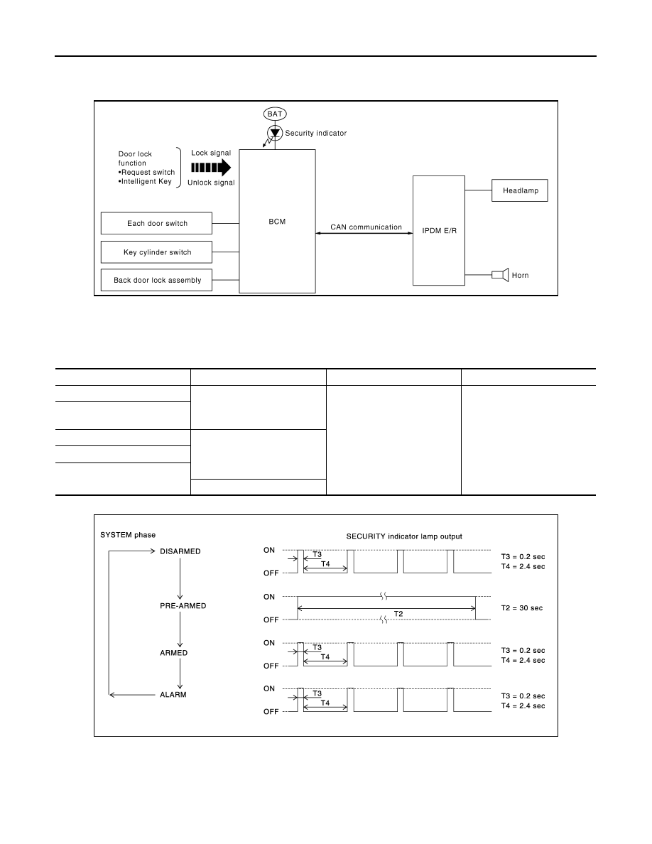
System Diagram
INFOID:0000000003586649
System Description
INFOID:0000000003586650
INPUT/OUTPUT SIGNAL CHART
OPERATION FLOW
SETTING THE VEHICLE SECURITY SYSTEM
Initial Condition
• Ignition switch is in OFF position.
Disarmed Phase
JMKIA1873GB
Switch
Input signal to BCM
BCM system
Actuator
All door switch
Open or close
Vehicle security system
• IPDM E/R
• Head lamp
• Horn
• Security indicator lamp
Back door lock assembly (door
switch)
Door key cylinder switch
Lock or unlock
Door request switch
Intelligent Key
Panic alarm
PIIA1367E
VEHICLE SECURITY SYSTEM
SEC-21
< FUNCTION DIAGNOSIS >
[INTELLIGENT KEY SYSTEM]
C
D
E
F
G
H
I
J
L
M
A
B
SEC
N
O
P
• When any door or back door is open, the vehicle security system is set in the disarmed phase on the
assumption that the owner is inside or near the vehicle.
• When the vehicle security system is in the disarmed phase, the security indicator lamp blinks every 2.4 sec-
onds.
Pre-armed Phase and Armed Phase
When the following operation is performed, the vehicle security system turns into the “pre-armed” phase. (The
security indicator lamp illuminates.)
1.
BCM receives LOCK signal from front door request switch, Intelligent Key or door key cylinder, after back
door and all doors are closed.
2.
The security indicator lamp illuminates for 30 seconds. Then, the system automatically shifts into the
“armed” phase.
CANCELING THE SET VEHICLE SECURITY SYSTEM
When one of the following operations is performed, the armed phase is canceled.
1.
Unlock the all doors with the door request switch, Intelligent Key or door key cylinder.
2.
Turn ignition switch “ON” or “ACC” position.
CANCELING THE ALARM OPERATION OF THE VEHICLE SECURITY SYSTEM
When unlocking the all doors with the door request switch, Intelligent Key or door key cylinder switch the alarm
operation is canceled.
ACTIVATING THE ALARM OPERATION OF THE VEHICLE SECURITY SYSTEM
Check that the system is in the armed phase. (The security indicator lamp blinks every 2.4 seconds.)
When the following operation 1 or 2 is performed, the system sounds the horns and flashes the headlamps for
about 50 seconds.
1.
Back door or any door is opened during armed phase.
2.
Disconnecting and connecting the battery connector before canceling armed phase.
PANIC ALARM OPERATION
Intelligent Key system may or may not operate vehicle security system (horn and headlamps) as required.
When the Intelligent Key system is triggered, ground is supplied intermittently to both headlamp relay and horn
relay.
When headlamp relay and horn relay are energized, then power is supplied to headlamps (high beam and low
beam) and horns (high and low).
The headlamps flash and the horn sounds intermittently.
The alarm automatically turns off after 50 seconds or when BCM receives any signal from Intelligent Key, door
request switch or door key cylinder.
SEC-22
< FUNCTION DIAGNOSIS >
[INTELLIGENT KEY SYSTEM]
VEHICLE SECURITY SYSTEM
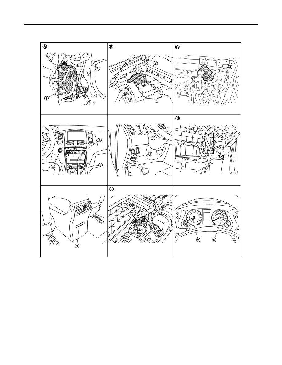
Component Parts Location
INFOID:0000000003736198
1.
BCM M118, M119, M121, M122, M123
2.
IPDM E/R E5, E6, E7
3.
Remote keyless entry receiver
M104
4.
Push-button ignition switch M50
5.
Unified meter and A/C amp. M66, M67 6.
Inside key antenna (instrument
center) M131
7.
Key slot M22
8.
ECM E107
9.
Inside key antenna (console)
M146
10. Inside key antenna (luggage room) B228 11.
Combination meter (KEY warning
lamp) M53
12. Combination meter (security indi-
cator) M53
A.
Dash side lower (passenger side)
B.
Engine room dash panel (RH)
C.
Behind the instrument assist low-
er panel
D.
Behind the instrument assist lower panel E.
Under the rear seat seatback
JMKIA2109ZZ
VEHICLE SECURITY SYSTEM
SEC-23
< FUNCTION DIAGNOSIS >
[INTELLIGENT KEY SYSTEM]
C
D
E
F
G
H
I
J
L
M
A
B
SEC
N
O
P
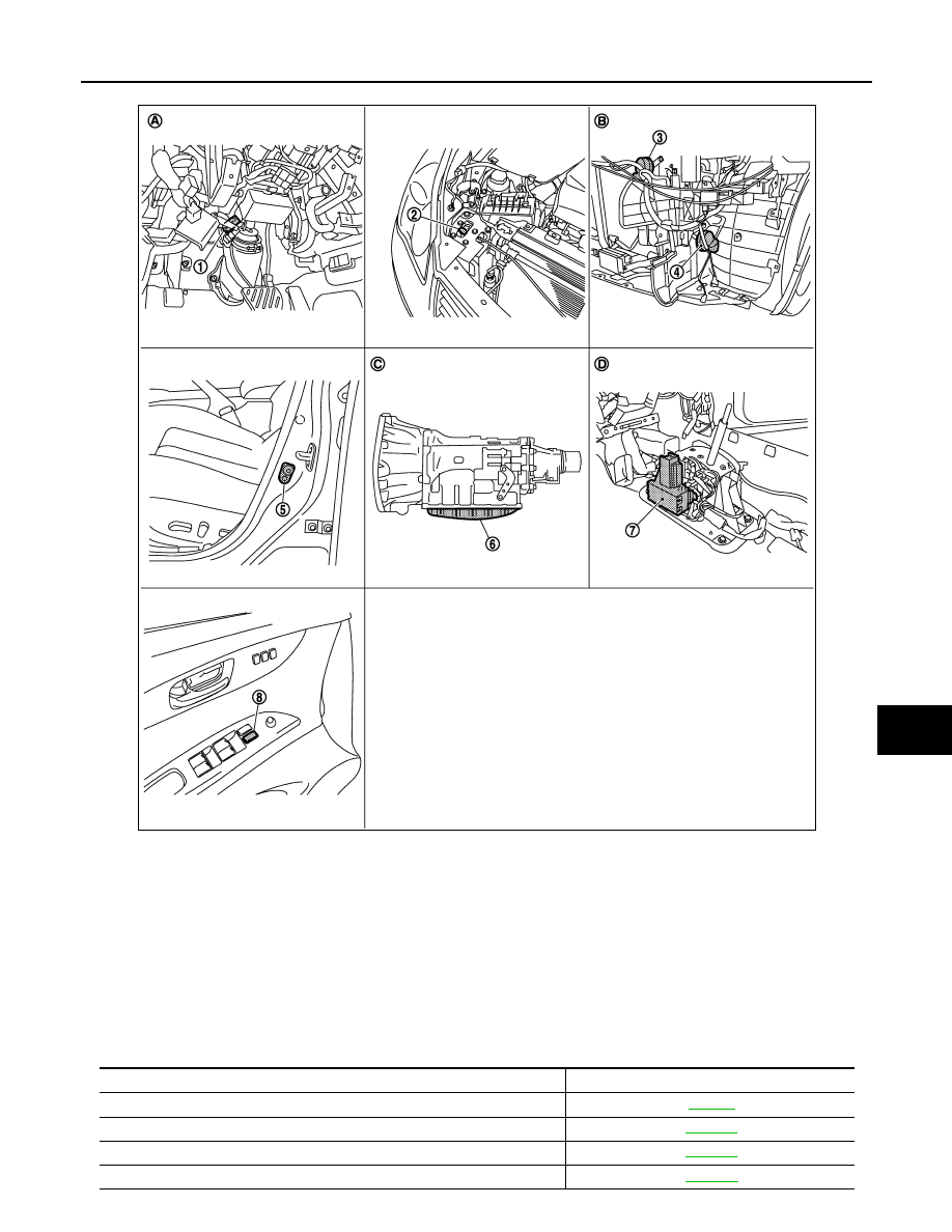
Component Description
INFOID:0000000003586652
1.
Stop lamp switch E110
2.
Hood switch E30
3.
Horn (high) E61, E62
4.
Horn (low) E69, E70
5.
Front door switch (driver side) B16
6.
TCM F151 (built into A/T assembly)
7.
Control device (detention switch)
M137
8.
Power window main switch (door
lock and unlock switch) D8, D9
A.
Behind the instrument driver lower
cover
B.
Behind the front bumper
C.
A/T assembly
D.
View with the center console assem-
bly removed
JMKIA2110ZZ
Component Reference
BCM
Horn relay 1
Horn relay 2
Security indicator lamp
Нет комментариевНе стесняйтесь поделиться с нами вашим ценным мнением.
Текст