Infiniti F50. Manual — part 831

WASHER SYSTEM
WW-11
C
D
E
F
G
H
I
J
L
M
A
B
WW
CONSULT-II BASIC OPERATION
1.
With the ignition switch OFF, connect “CONSULT-II” and “CON-
SULT-II CONVERTER” to data link connector, and turn the igni-
tion switch ON.
2.
Touch “START (NISSAN BASED VHCL)”.
3.
Touch “IVMS”.
If “IVMS” is not indicated, go to
.
4.
Check the model specification, and touch either “WITH SUN-
ROOF” or “WITHOUT SUNROOF” on the “SELECT SYS
COND” SCREEN.
5.
Touch “OK”. If the selection is wrong, touch “CANCEL”.
6.
Select the desired part to be diagnosed on the “SELECT TEST
ITEM” screen.
IVMS diagnosis
part
Check item and diagno-
sis mode
Description
WIPER
WORK SUPPORT
Changes the setting for each function.
DATA MONITOR
Displays data relative to BCM input signals and various control related data for each
system.
ACTIVE TEST
Gives a drive signal to a load to check the operation.
BCM PART NUMBER.
Displays BCM part No.
SHIA0179E
SKIA3098E
PIIA0183E
PIIA0184E

WW-12
WASHER SYSTEM
WORK SUPPORT
Operation Procedure
1.
Touch “WIPER” on the “SELECT TEST ITEM” screen.
2.
Touch “WORK SUPPORT” on the “SELECT DIAG MODE” screen.
3.
Touch “WIP INT VHCL SPD ADJ” on the “SELECT WORK ITEM” screen.
4.
Touch “START”.
●
Wiper intermittent speed control by vehicle speed can be canceled or resumed.
5.
Touch “CURRENT SETTING” for changing “CURRENT SETTING”.
For no changing “CURRENT SETTING”, touch “END”.
6.
Touch “END” after customizing is completed.
DATA MONITOR
Operation Procedure
1.
Touch “WIPER” on the “SELECT TEST ITEM” screen
2.
Touch “DATA MONITOR” on the “SELECT DIAG MODE” screen.
3.
Touch either “ALL SIGNALS” or “SELECTION FROM MENU” on the “DATA MONITOR” screen.
4.
Touch “START”.
Date Monitor Item
ACTIVE TEST
Operation Procedure
1.
Touch “WIPER” on the “SELECT TEST ITEM” screen.
2.
Touch “ACTIVE TEST” on the “SELECT DIAG MODE” screen.
3.
Touch the item to be tested, and check the operation.
4.
During the operation check, touching “OFF” deactivates the operation.
On Board Diagnosis
EKS001J0
●
IVMS can check communication diagnosis, switch monitor, and central locking system self diagnosis
using on board diagnosis.
●
Map lamps and step lamps (all seats) act as the indicators for the on board diagnosis.
DIAGNOSIS ITEM FOR FRONT WIPER AND WASHER SYSTEM
“CURRENT SETTING”
Wiper intermittent speed control.
“ON”
Activated
“OFF”
Inactivated
Monitored item
Description
IGN ON SW
Indicates “IGN [ON] / ACC or OFF [OFF]” condition of ignition switch signal.
INT SW
Indicates “ INT position [ON] / Others [OFF]” condition of front wiper switch signal.
WASH SW
Indicates “WASH position [ON] / Others [OFF]” condition of front wiper switch signal.
VHCL SPEED SE
Indicates “Vehicle is moving [RUN] / Vehicle stopped [STOP]” condition of vehicle speed signal.
WIPR AUTO STP
Indicates “INT or OFF position [IGN] / LO or HI position [OFF]” condition of front wiper switch sig-
nal.
INTRESIST
Indicates “ Intermittent resistance value [approx. 0 to 1]” condition front wiper switch signal.
Test item “WIPER AMP”
Front wiper motor operation
“ON”
Operate
“OFF”
Stop
Diagnosis item
Description
Switch monitor
It can checks wiper and washer switch.
WASHER SYSTEM
WW-13
C
D
E
F
G
H
I
J
L
M
A
B
WW
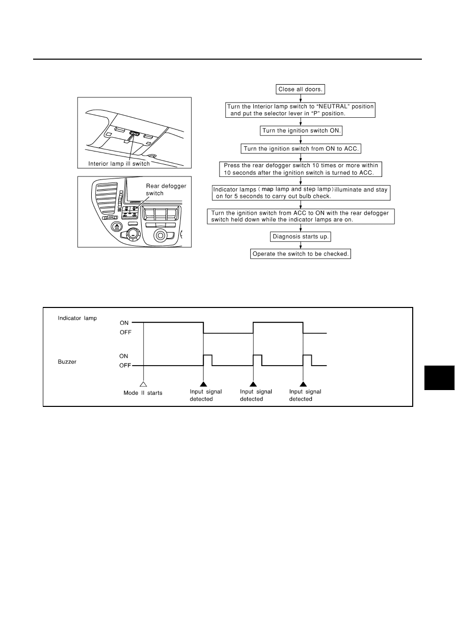
SWITCH MONITOR
How to Perform Switch Monitor
Diagnosis Result Display
●
Detects the status change (switch ON/OFF operation) of the switch to be checked, and turns on/off the
indicator lamps (the map lamp and step lamp). Also sounds the buzzer for 0.5 seconds.
●
If a malfunction is detected, no indicator lamp and buzzer react.
Cancel of Switch Monitor
●
The ignition switch is turned OFF.
●
Drive the vehicle at more than 7 km/h (4MPH).
SIIA0411E
SEL960V

WW-14
WASHER SYSTEM
Intermittent Wiper Does Not Operate
EKS001J1
1.
CHECK INTERMITTENT FRONT WIPER SWITCH INPUT SIGNAL
With CONSULT-II
See “INT SW” in “DATA MONITOR” mode.
NOTE:
When “Data monitor” is operating, intermittent wiper do not operate.
Without CONSULT-II
Check front wiper switch (INT) in switch monitor mode, refer to
.
OK or NG
OK
>> GO TO 2.
NG
>> Check the following.
●
Front wiper switch
●
Harness for open or short between BCM and front wiper switch
●
Front wiper switch ground circuit
2.
CHECK WIPER AUTO STOP SIGNAL
With CONSULT-II
See “WIPR AUTO STP” in “DATA MONITOR” mode, and turn front
wiper switch to LO or HI position.
Without CONSULT-II
1.
Turn ignition switch to ON position.
2.
Turn front wiper switch to LO or HI position.
3.
Check voltage between BCM harness connector E204 terminal
124 (SB) and ground.
OK or NG
OK
>> GO TO 3.
NG
>> Check the following.
●
Front wiper motor
●
Front wiper motor ground circuit
●
Harness for open or short between BCM and front wiper motor
When front wiper switch is in
INT position
: ON
When front wiper switch is in
OFF position
: OFF
SEL503W
When front wiper switch is in
INT or OFF position
: IGN
When front wiper switch is in
LO or HI
: GND
SEL504W
Wiper is moving
:Approx. 0V
Wiper is stopped
: Approx. 12V
SKIA4237E
Нет комментариевНе стесняйтесь поделиться с нами вашим ценным мнением.
Текст