Infiniti F50. Manual — part 86
DTC P1845 ATF PRESSURE SWITCH 5
AT-229
D
E
F
G
H
I
J
K
L
M
A
B
AT
Diagnostic Procedure
ECS0088Y
1.
INPUT SIGNALS
With CONSULT-II
1.
Start engine.
2.
Select “ECU INPUT SIGNALS” or “MAIN SIGNALS” in “DATA
MONITOR” mode for “A/T” with CONSULT-II.
3.
Accelerate vehicle in the “D” position (1st
Þ
2nd gear), and con-
firm the ON/OFF actuation of the “ATF PRES SW 5”.
OK or NG
OK
>> GO TO 4.
NG
>> GO TO 2.
2.
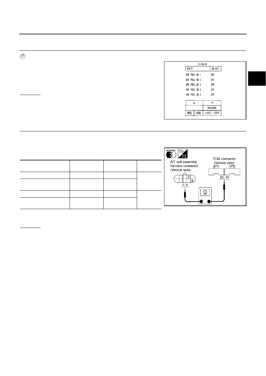
CHECK HARNESS BETWEEN TCM AND A/T UNIT ASSEMBLY HARNESS CONNECTOR
1.
Turn ignition switch to “OFF” position.
2.
Disconnect TCM connector.
3.
Check continuity between A/T unit assembly harness connector
and TCM connector.
4.
If OK, check harness for short to ground and short to power.
5.
Reinstall any part removed.
OK or NG
OK
>> GO TO 3.
NG
>> Repair open circuit or short to ground or short to power in harness or connectors.
PCIA0067E
Item
Connector No.
Terminal No.
(Wire color)
Continuity
TCM
F103
22 (P/B)
Yes
A/T unit assembly harness
connector
F26
6 (P/B)
TCM
F104
40 (Y/G)
Yes
A/T unit assembly harness
connector
F26
2 (Y/G)
SCIA3101E

AT-230
DTC P1845 ATF PRESSURE SWITCH 5
3.
CHECK TERMINAL CORD ASSEMBLY
1.
Remove oil pan. Refer to
AT-289, "Control Valve Assembly"
2.
Disconnect A/T unit assembly harness connector and control valve assembly harness connector.
3.
Check continuity between A/T unit assembly harness connector
and control valve assembly harness connector.
4.
If OK, check harness for short to ground and short to power.
OK or NG
OK
>> Replace the control valve assembly. Refer to
AT-289, "Control Valve Assembly"
NG
>> Repair open circuit or short to ground or short to power in harness or connectors.
4.
CHECK DTC
Perform DTC confirmation procedure. Refer to
AT-227, "DTC Confirmation Procedure"
OK or NG
OK
>> INSPECTION END
NG
>> GO TO 5.
5.
PERFORM TCM INSPECTION
1.
Perform TCM input/output signal inspection.
2.
If NG, recheck TCM pin terminals for damage or loose connection with harness connector.
OK or NG
OK
>> Replace the control valve assembly. Refer to
AT-289, "Control Valve Assembly"
NG
>> Repair or replace damaged parts.
Item
Connector No.
Terminal No. (Wire color)
Continuity
A/T unit assembly
harness connector
F26
2 (R)
Yes
Control valve assem-
bly harness connec-
tor
F302
10 (R)
A/T unit assembly
harness connector
F26
6 (GY)
Yes
Control valve assem-
bly harness connec-
tor
F302
14 (GY)
SCIA3102E

DTC P1846 ATF PRESSURE SWITCH 6
AT-231
D
E
F
G
H
I
J
K
L
M
A
B
AT
DTC P1846 ATF PRESSURE SWITCH 6
PFP:25240
Description
ECS0088Z
Fail-safe function to detect high & low reverse clutch solenoid valve condition.
On Board Diagnosis Logic
ECS00890
●
This is not an OBD-II self-diagnostic item.
●
Diagnostic trouble code “ATF PRES SW 6/CIRC” with CONSULT-II is detected, when TCM detects that
actual gear ratio is normal, and relation between gear position and condition of ATF pressure switch 6 is
irregular during depressing accelerator pedal. (Other than during shift change)
Possible Cause
ECS00891
●
ATF pressure switch 6
●
Harness or connectors
(The switch circuit is open or shorted.)
DTC Confirmation Procedure
ECS00892
CAUTION:
Always drive vehicle at a safe speed.
NOTE:
If “DTC Confirmation Procedure” has been previously conducted, always turn ignition switch “OFF”
and wait at least 10 seconds before conducting the next test.
After the repair, perform the following procedure to confirm the malfunction is eliminated.
WITH CONSULT-II
1.
Start engine.
2.
Accelerate vehicle to maintain the following condition.
ACCELE POS: 1.5/8 - 2.0/8
Selector lever: “D” position
Gear position: 2nd
Þ
3rd Gear (HLR/C ON/OFF)
3.
Perform step “2” again.
4.
Turn ignition switch to “OFF” position, then perform step “1” to
“3” again.
5.
Check “SELF-DIAG RESULTS” mode for “A/T” with CONSULT-
II.
If DTC (P1846) is detected, go to
.
If DTC (P1767) is detected, go to
AT-199, "Diagnostic Procedure"
SAT014K

AT-232
DTC P1846 ATF PRESSURE SWITCH 6
Wiring Diagram — AT — FPSW6
ECS00893
TCM terminal and data are reference value. Measured between each terminal and ground.
TCWM0031E
Terminal
No.
Wire
color
Item
Condition
Data (Approx.)
26
G/Y
PSC2
(pressure switch 6)
When
vehicle
cruises
When high & low reverse clutch solenoid valve “ON”.
0V
When high & low reverse clutch solenoid valve “OFF”.
Battery voltage
Нет комментариевНе стесняйтесь поделиться с нами вашим ценным мнением.
Текст