Infiniti F50. Manual — part 83

DTC P1815 MANUAL MODE SWITCH
AT-217
D
E
F
G
H
I
J
K
L
M
A
B
AT
Diagnostic Procedure
ECS0088E
1.
CHECK MANUAL MODE SWITCH CIRCUIT (WITH CONSULT-II)
With CONSULT-II
1.
Turn ignition switch to “ON” position. (Do not start engine.)
2.
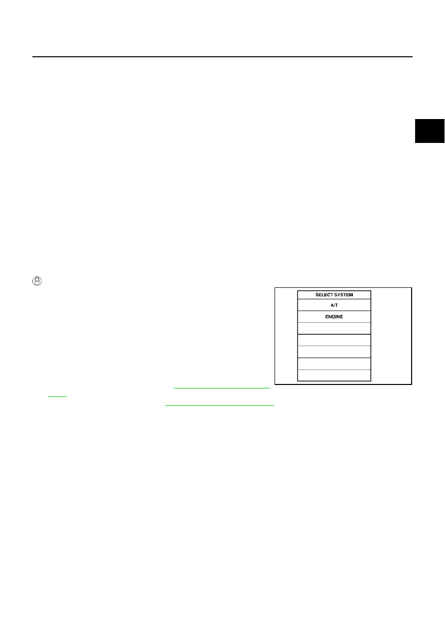
Select “ECU INPUT SIGNALS” in “DATA MONITOR” mode for
“A/T” with CONSULT-II.
3.
Read out ON/OFF switching action of the “MANU MODE SW”,
“NON M-MODE SW”, “UP SW LEVER”, “DOWN SW LEVER”.
OK or NG
OK
>> GO TO 4.
NG
>> GO TO 3.
2.
CHECK MANUAL MODE SWITCH CIRCUIT (WITHOUT CONSULT-II)
Without CONSULT-II
Drive vehicle in the manual mode, and confirm that the actual gear position and the meter's indication of the
position mutually coincide when the selector lever is shifted to the “+ (up)” or “- (down)” side (1st
⇔
5th gear).
OK or NG
OK
>> GO TO 4.
NG
>> GO TO 3.
3.
DETECT MALFUNCTIONING ITEM
Check the following items.
●
Power supply. Refer to
.
●
Manual mode switch. Refer to
AT-218, "Component Inspection"
●
Pin terminals for damage or loose connection with harness connector.
●
Open circuit or short to ground or short to power in harness or connector for A/T device (manual mode
switch).
OK or NG
OK
>> GO TO 4
NG
>> Repair or replace damaged parts.
4.
CHECK DTC
Perform DTC confirmation procedure. Refer to
AT-215, "DTC Confirmation Procedure"
OK or NG
OK
>> INSPECTION END
NG
>> Replace the control device assembly.
PCIA0064E

AT-218
DTC P1815 MANUAL MODE SWITCH
Component Inspection
ECS0088F
MANUAL MODE SWITCH
Check continuity between terminals.
Position Indicator Lamp
ECS0088G
DIAGNOSTIC PROCEDURE
1.
CHECK INPUT SIGNALS (WITH CONSULT-II)
With CONSULT-II
1.
Start engine.
2.
Select “MAIN SIGNALS” in “DATA MONITOR” mode for A/T with
CONSULT-II and read out the value of “GEAR”.
3.
Drive vehicle in the manual mode, and confirm that the actual
gear position and the meter's indication of the position mutually
coincide when the select lever is shifted to the “+ (up)” or “-
(down)” side (1st
⇔
5th gear).
OK or NG
OK
>> INSPECTION END
NG
>> Check the following items.
Position Indicator Lamp Symptom Chart
Item
Position
Connector
No.
Terminal No.
(Unit side)
Continuity
Manual mode
(select) switch
Auto
M97
4 - 5
Yes
Manual
1 - 4
UP switch
Up
3 - 4
DOWN switch
Down
2 - 4
SCIA1769E
PCIA0065E
Items
Presumed location of trouble
The actual gear position does not change, or shifting into the
manual mode is not possible (no gear shifting in the manual mode
possible).
The position indicator lamp is not indicated.
Manual mode switch
Refer to
AT-215, "DTC P1815 MANUAL MODE SWITCH"
.
A/T main system (Fail-safe function actuated)
●
Refer to
AT-87, "SELF-DIAGNOSTIC PROCEDURE (WITH
.
The actual gear position changes, but the position indicator lamp
is not indicated.
Execute the self-diagnosis function.
●
Refer to
AT-87, "SELF-DIAGNOSTIC PROCEDURE (WITH
.
The actual gear position and the indication on the position indica-
tor lamp do not coincide.
Execute the self-diagnosis function.
●
Refer to
AT-87, "SELF-DIAGNOSTIC PROCEDURE (WITH
.
Only a specific position or positions is/are not indicated on the
position indicator lamp.
Check the combination meter.
Refer to
DTC P1841 ATF PRESSURE SWITCH 1
AT-219
D
E
F
G
H
I
J
K
L
M
A
B
AT
DTC P1841 ATF PRESSURE SWITCH 1
PFP:25240
Description
ECS0088H
Fail-safe function to detect front brake clutch solenoid valve condition.
On Board Diagnosis Logic
ECS0088I
●
This is not an OBD-II self-diagnostic item.
●
Diagnostic trouble code “ATF PRES SW 1/CIRC” with CONSULT-II is detected, when TCM detects that
actual gear ratio is normal, and relation between gear position and condition of ATF pressure switch 1 is
irregular during depressing accelerator pedal. (Other than during shift change)
Possible Cause
ECS0088J
●
ATF pressure switch 1
●
Harness or connectors
(The switch circuit is open or shorted.)
DTC Confirmation Procedure
ECS0088K
CAUTION:
Always drive vehicle at a safe speed.
NOTE:
If “DTC Confirmation Procedure” has been previously conducted, always turn ignition switch “OFF”
and wait at least 10 seconds before conducting the next test.
After the repair, perform the following procedure to confirm the malfunction is eliminated.
WITH CONSULT-II
1.
Start engine.
2.
Accelerate vehicle to maintain the following condition.
ACCELE POS: 1.5/8 - 2.0/8
Selector lever: “D” position
Gear position: 3rd
Þ
4th Gear (FR/B ON/OFF)
3.
Perform step “2” again.
4.
Turn ignition switch to “OFF” position, then perform step “1” to
“3” again.
5.
Check “SELF-DIAG RESULTS” mode for “A/T” with CONSULT-
II.
If DTC (P1841) is detected, go to
.
If DTC (P1757) is detected, go to
AT-181, "Diagnostic Procedure"
SAT014K

AT-220
DTC P1841 ATF PRESSURE SWITCH 1
Wiring Diagram — AT — FPSW1
ECS0088L
TCM terminal and data are reference value. Measured between each terminal and ground.
TCWM0028E
Terminal
No.
Wire
color
Item
Condition
Data (Approx.)
35
B/Y
PSB2 (pressure
switch 1)
When
vehicle
starts
When front brake solenoid valve “OFF”.
Battery voltage
When front brake solenoid valve“ ON”.
0V
Нет комментариевНе стесняйтесь поделиться с нами вашим ценным мнением.
Текст